
Comprehensive Testing Capabilities
Concepts NREC provides high-quality and accurate CMM inspection with fast turnaround for all of the parts we manufacture. We have a temperature-controlled inspection facility that is equipped with a full complement of standard metrological tools for dimensional inspection of critical components, whether manufactured in-house or by subcontractors.
Concepts NREC can supplement a client's current inspection operation with quick turnaround of short- and long-term inspections, reduce their manpower requirements, and provide second- and third-party certification of parts. Quality-control records are maintained to the highest government and industrial standards.
-
Coordinate Measuring Machine (CMM) inspection
-
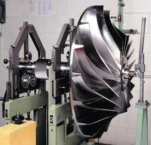
Dynamic balancing and modal analysis
-
Inspection and testing to validate integrity and performance
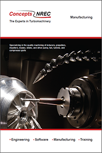
Manufacturing Brochure
Our specialty is manufacturing prototypes and short production runs of your most challenging turbomachinery parts on our 5-axis CNC machines.