The Gyroscopic Effect
This post covers one of the fundamental issues that makes rotordynamics a unique subject: The Gyroscopic Effect. The gyroscopic effect can be observed in the behavior of spinning tops, fidget...


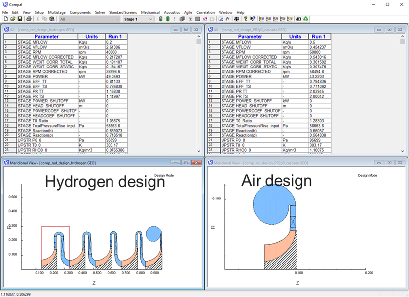
The biggest reason to use an integrated turbomachinery design and analysis environment is speed. Basically, having everything you need in one place makes a big difference!
I have been designing turbine and hot gas path components for more than 20 years. The most common cause of problems was the transfer of data from one software application to another. Every time you make the transfer, whether it be via IGES, STEP or CAD native formats you seem to lose something along the way. At best, it is just lost time… time taken to clean-up or repair, perhaps to create a suitable cyclic sector, delete unwanted features and components, or create additional geometry etc. But the biggest thing that you lose is part-history, you end up with a ‘dumb solid’, you can’t, for instance, just switch off the blade fillet, or change its radii. The lesson I learned during those years was don’t transfer data if you don’t have to!
So, if the main advantage of an integrated FEA system is that there is no transfer of geometry data, then the next most important advantage is just how early in the design process you can begin assessing the design’s suitability. Once you have done your basic mean-line based aero-design you can run FEA utilizing mapped aero boundary conditions from that mean-line analysis. So rather than the mechanical analysis being the final test of the design loop it can now become an integral part of the design process that if used effectively will significantly reduce the length of the design process loop and increase understanding of the design’s limitations.
The turbomachinery specific, integrated FEA pre-processor takes care of dividing your model into a suitable blade centered cyclic sector and the mapping of flow results onto the blade surfaces automatically. The most suitable cyclic symmetry sector for the particular geometry is generated instantly rather than it being a relatively time consuming CAD based process. The pre-processors also have a range of fully parameterized geometry features available that can be applied in combination to create your particular machine configuration.
Then there are mapped boundary conditions; blade-loading can be applied very quickly and easily, usually at the click of a check-box, whether they be face pressure loads or thermal analysis temperatures and convection coefficients. As mentioned earlier, boundary conditions can be sourced from aero analysis results that have been performed at any point in the design process.
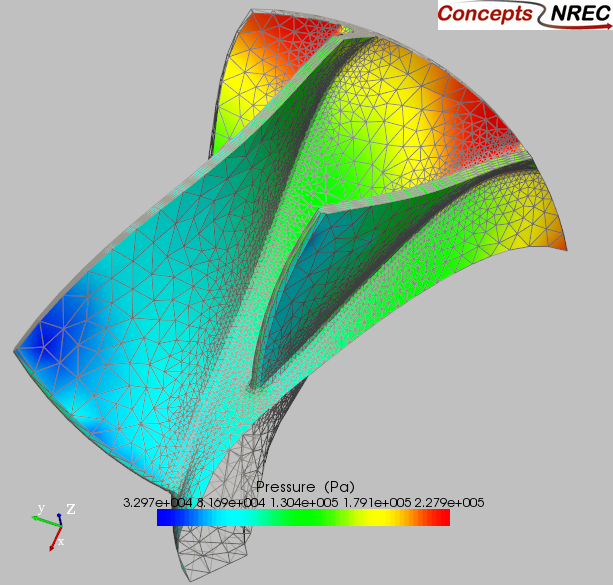
Figure 1. Mapped fluid pressure boundary conditions on a turbocharger compressor wheel FEA grid.
Turbomachinery specific boundary conditions are also available; they are a subset of the many types of prescribed boundary conditions used by generalized FE codes. Having limited options such as cyclic, limited displacement constraint types, pre-applied rotational loads etc speeds the process of analysis model setup.
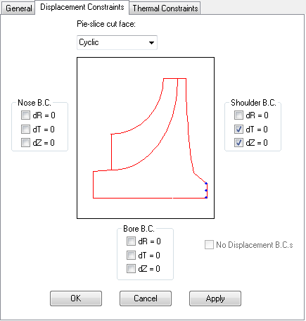
Fig 2 Turbomachinery targeted boundary condition selection makes for fast model setup.
Use of solver specific conditions such as transfer of thermal solver results to the static solver for thermal stress calculation and subsequent transferal of static stress analysis results to the modal solver to model pre or stress stiffening effects. Other common solver selections useful for turbomachinery FE analysis such as spin softening for modal analysis, temperature dependent material properties for all solvers etc are also close at hand and easily specified. Both spin softening and stress stiffening have significant impact on the predicted natural frequencies of a blade/vane and can be applied together where applicable.
Other advantages include the production of turbomachinery specific model properties. Sector volume, mass, and polar moments, IP and IT are calculated as full 360° rotor properties at model generation time. Nothing very complicated, it is just convenient and saves you time and is made possible because the FEA application is targeted at geometry made up of common entities.
Turbomachinery specific post-processing, displacements and stresses expressed as radial, hoop or axial components rather than x, y, z. Pre-presented on key surfaces such as hub fillet, shroud fillet, bore etc so that data is made quickly available without digging through the 3d model for locations of peak displacements, stresses or temperatures. Identified surface results make it easy to decide which features might need modifying in the event of the component not meeting life cycle requirements. For example, the Goodman diagram in fig 3 you can clearly see that blade and hub fillet changes would be required if you were to increase component life to 10e5 cycles.
The results can also be quickly presented in typical turbomachinery results format, Goodman diagram for static stress calculated low cycle fatigue life based on start and stop cycles, Campbell and/or Interference/SAFE diagrams for the prediction of possible conflicts of natural mode frequencies with engine stimuli. These are all very powerful tools for the estimation of component life in the harsh environments that is often encountered by turbomachinery gas path components.
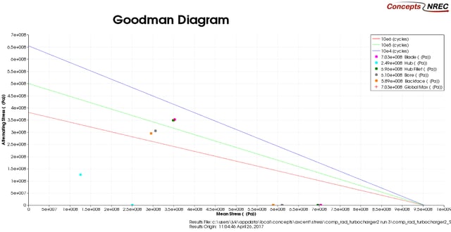
Fig 3. Static stress analysis results presented on a Goodman diagram
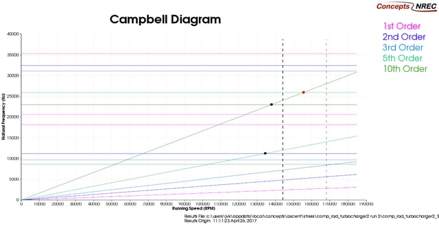
Fig 4 Modal analysis results presented on a Campbell diagram
Tags: CAE Software
This post covers one of the fundamental issues that makes rotordynamics a unique subject: The Gyroscopic Effect. The gyroscopic effect can be observed in the behavior of spinning tops, fidget...
Hydrogen is attracting a lot of interest in different circles these days from: propulsion, to energy storage, to personal transportation. The most obvious benefit of hydrogen fuel is a total lack of...

Because of its promise as a non-polluting fuel, hydrogen is currently a very popular topic among the energy and turbomachinery communities. If hydrogen is reacted with pure oxygen, the thermal energy...