A Brief Overview of Adaptive Machining
As engineers planning and designing with CAD/CAM tools,we are developing processes in a theoretical world. It isn’t until you put on your boots, get in front of the machine, and start lettingchips fly


When designing compressors, engineers often use ruled-surface blades with the goal of making a shape that’s easily manufactured on a 5-axis machine. Theses blades can be quickly machined in one pass by aligning the side of a cutting tool to the rulings. This process is often referred to as “flank milling.” The alternative is to make many passes with the tool tip, a process known as “point milling”. For the right application, flank milling is often favored for shorter cutting times and better surface quality, but there are some caveats.
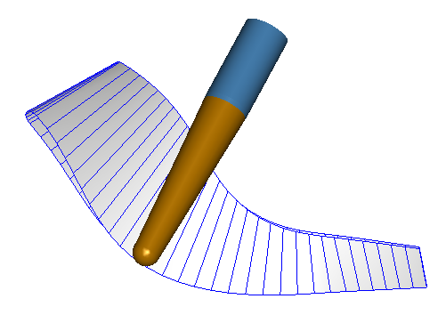
One major consideration is the geometric deviation from flank-milling a ruled surface. Initially it seems that you can just simply align the tool to the rulings. But, in fact, this approach gives a deviation that can be significant. On simple blades, like diffuser vanes, the tool can indeed be aligned to the rulings with zero deviation. However, most compressor blades have some “twist” angle between the tip and root contours. Simply aligning the tool vector with the ruling gives a deviation that increases with the twist. In fact, the resulting surface is not a ruled-surface at all. The deviation also increases with tool size; for example, only an infinitely slender tool could sweep out a twisted blade shape with zero deviation. Given these considerations, advanced calculations are needed to find tool orientations that minimize the geometric deviation to within an acceptable machining tolerance. Yet another approach is to let the design be the non-ruled shape swept by the tool. By contrast, positioning a tool to cut with just the ball tip is a relatively simple calculation.
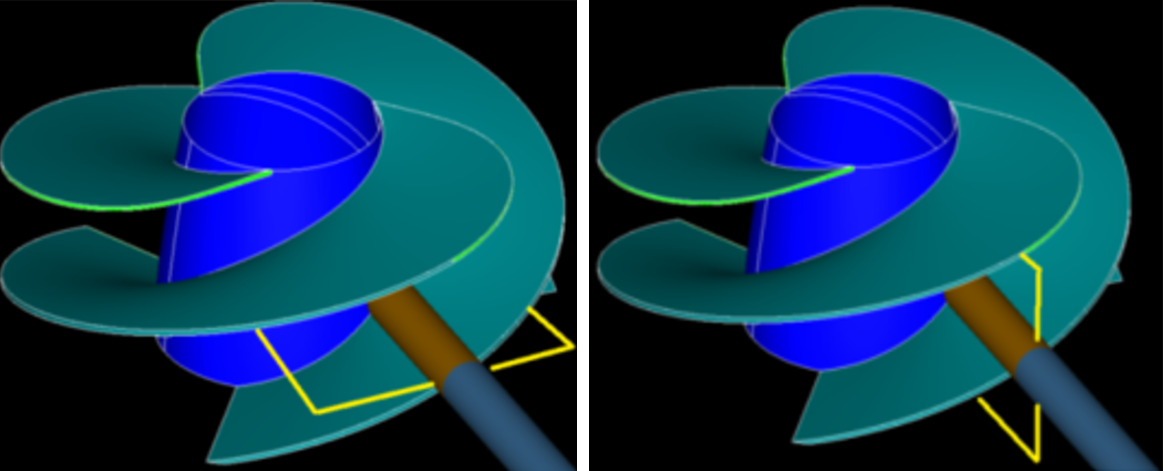
Another pitfall of flank milling, especially on compressor blades, is runaway rotary axis motion. 5-axis machines generally have three translation axes and two rotary axes. The rotary axes adjust the inclination of the tool relative to the workpiece. However, problems often occur at the trailing edge of compressors, where the ruled surface definition requires the tool to stand nearly parallel to the part axis of rotation. This creates a dangerous situation where small adjustments to the tool orientation can lead to large, unexpected rotary motions. There can be up to 180 degrees of rotary motion when the tool is only expected to move a short distance along the workpiece. The results can be disastrous for the part, the tool, or the milling machine. Here again, an advanced programming system, like MAX-5™, part of our MAX-PAC™CAM Software, is needed to detect and avoid this runaway motion, creating a tool trajectory that forms the blade within tolerance, while maintaining a safe, smooth motion of the milling machine. Programming for point milling is comparatively easier because the tool can be freely oriented and need not be leaned against the blade.
The practical machining considerations of flank milling are also more challenging than point milling. The tools are generally more expensive because they need cutting teeth along the full length, and are often conical in shape. Typically, solid carbide tooling is used for stiffness. The process is also sensitive to the geometry of the cutting teeth on the tool. Because the whole tool length is used, the cutting forces are much higher than cutting with just the tool tip. This usually results in deflection of the tool, or part, that must be accounted for during programming, especially when attempting to flank-mill around a thin leading edge. It is also more difficult with flank milling than point milling to arrive at a combination of cutting feed and RPM values to create a quality surface finish quickly.
Ruled-surface blades are designed for manufacturing and are still considered “easier” than parts with more complex blade shapes. Ironically, the flank milling process turns out to be more challenging than point milling. However, the rewards are a shorter cycle time and a near mirror surface finish.
MAX-5 and Deviation: To help with deviation issues, our algorithm analyzes and assesses the deviation and compensates for it, to produce parts that meet very tight tolerances. To see a demonstration of MAX-5 in action, click on the video below.
Tags: CAM Software, MAX-PAC, Manufacturing

As engineers planning and designing with CAD/CAM tools,we are developing processes in a theoretical world. It isn’t until you put on your boots, get in front of the machine, and start lettingchips fly
Turbopumps pose many challenges when trying to manufacture high quality CNC toolpaths. They are often made of difficult to machine materials such as Inconel, have sharp leading edges, demanding...
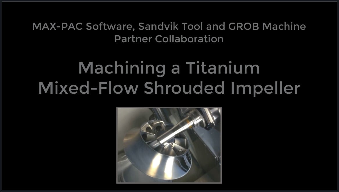
Mixed flow impellers can be challenging, often requiring multiple set-ups due to the ~45° exit angle. Check out how we utilized multiple MAX-PAC cutting strategies in this collaboration with GROB and...