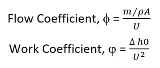
Two often used quantities to characterize turbomachinery are flow coefficient and work coefficient. The two are generally represented as Φ for flow coefficient and φ for work coefficient. The mathematical definition for the two quantities are as follows:
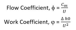
Cm is the meridional velocity (meridional velocity is the component of velocity in the radial and axial plane). U is the local rotational speed (radius*rotational velocity) and Δh0 is the change in total enthalpy or energy of the fluid.
Although not immediately obvious, the two quantities are directly related to the shape of the velocity triangle. This becomes more clear when we consider the Euler turbomachinery equation:
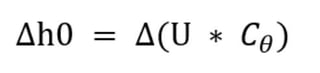
Where Cθ is the tangential velocity of the fluid.
Let's take a simple axial compressor example to help visualize the equations. The figure on the left is a simple compressor stage with the rotor (in blue) moving to the right and the stator (in red) which is not rotating. The absolute velocity (C) is in red. The relative velocity (W) is blue and represents what the rotor actually “sees” of the fluid. The absolute velocity is the vector sum of the relative velocity and the local wheel speed (U) shown in green.
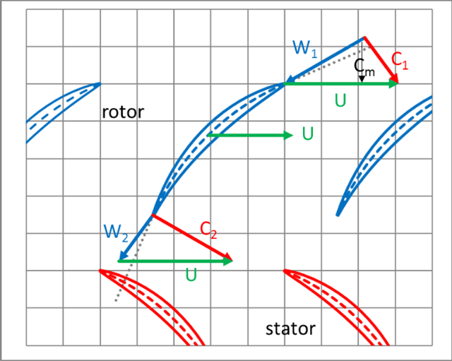
Since this is a purely axial example, there is no difference between the outflow and inflow radius and therefore the wheel speed U is also uniform. The Euler turbomachinery equation reduces to:
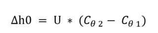
Plugging this into the equation for work coefficient we get:

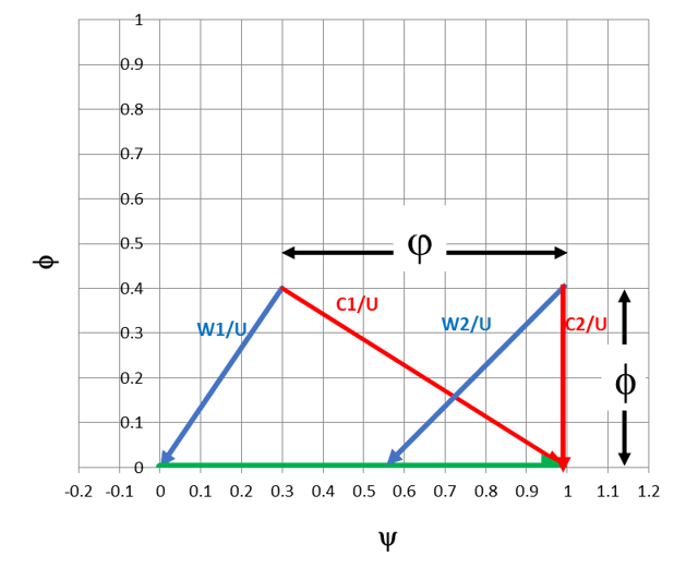
If we normalize the fluid velocities by U and plot them together, we get a handy graphical representation of the coefficients:
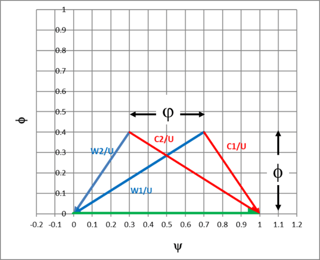
We can see immediately that the shape of the triangle and the resulting angles are determined by the coefficients. There is, actually, a third variable at play, which is the reaction of the stage (see blog: Reaction Verses Impulse). The reaction of the stage is the overall pressure split between the rotor and stator. Sometimes the reaction is defined in terms of energy, but the principle is the same. In this example, the reaction of the stage is 50% and the velocities that the rotor sees (relative) and the velocities that the stator sees (absolute) are identical. This gives two symmetrical triangles balanced about the center of the plot.
The situation becomes a bit more complex with a radial machine. Since the wheel speeds are no longer equal, the coefficients can be defined differently. The typical convention is to take the largest radius (exit radius for a compressor or pump and inlet radius for a radial turbine) as the basis for the U value. The equation can be recast as:
Where m is the mass flow, ρ is the density, and A is the area.
A radial turbine with zero exit swirl (a reasonable design target) makes no contribution to the Euler work, thus the work coefficient is a function of the inlet condition alone. Plotting this in a similar basis as the axial compressor gives us the triangle distribution below.
Flow and work coefficients are two of the most common means of classifying turbomachinery stages. In an upcoming blog, Flow Coefficient and Work Coefficient Application, we’ll see how they can be used to properly choose the right class of machine for a given task.
Be sure to read my blog on Specific Speed Demystified!