The Gyroscopic Effect
This post covers one of the fundamental issues that makes rotordynamics a unique subject: The Gyroscopic Effect. The gyroscopic effect can be observed in the behavior of spinning tops, fidget...


Finding the root cause of a failure by narrowing down multiple overlaid symptoms can be a long and tedious process—and very often the true underlying problem is not what one might expect by a casual examination of the symptoms. That was the potential difficulty a customer of ours wanted to avoid when they investigated the catastrophic failure of a super-critical, feed-water pump used for a powerplant boiler.
Our customer provides rerating and reworking of industrial pumps. Their core capability is resolving mechanical problems through effective hydrodynamic (fluid flow path) design changes. For several years, they had been working with a state-owned electric power dispatcher to solve a serious vibration problem in the feedwater pumps used at two of its power-generation plants.
The five-stage pumps, installed more than 30 years ago, used a double-suction pump design with two impellers in the first stage so that each takes half of the full inlet flow. This configuration is typical in feed-water pump applications because it reduces NPSH (Net Positive Suction Head) and thereby reduces the potential for cavitation problems. The pump draws 28,000 hp from a steam turbine in a direct-drive arrangement and operates at speeds between 3,900 rpm and 5,200 rpm. Flow rate is 10,000 gpm, and outlet pressure is 12,000 ft. of head.
For many years, the pumps were being used close to their top load condition, but changing electrical demands gradually reduced load demands. Now the pumps have been operating at only 25% of their capacity during evening hours, and while being operated in this condition, the fourth-stage impeller of one machine failed catastrophically. The failure was of concern because there were more of these pumps at the plant.
Upon site inspection, our customer found a subsynchronous hydrodynamic instability at 80% BEP (Best Efficiency Point) which was thought to be an issue with the second through fifth (or “series”) stages, and another at 50% BEP which was thought to be an issue with the first (or “suction”) stage. At 3,900 rpm, the total vibration level was measured to be 3 to 4 mils, with the 10 Hz frequency alone contributing 2.0 to 2.5 mils.
Since there were multiple issues to resolve, it was decided to first address the most serious. The series stages were given new diffuser vane configurations with a higher vane count, and the 80% BEP instability disappeared. However, the 50% BEP instability was exacerbated, particularly in the 10 Hz region.
The next action was to address the suction stage with a similar change to a higher vane count in the diffusers. The suction-stage impellers were also examined and found to be far too high in suction specific speed (roughly 11,000), making them highly unstable at lower flow conditions. Further investigation revealed that the OEM had made a questionable design decision. Standard 20-inch-diameter impellers designed for operation at 3,600 rpm had been cut down to an 18-inch diameter for the faster 5,200 rpm condition. In so doing, the OEM designers had changed the impeller’s specific speed so significantly that the design was doomed for the faster speed application.
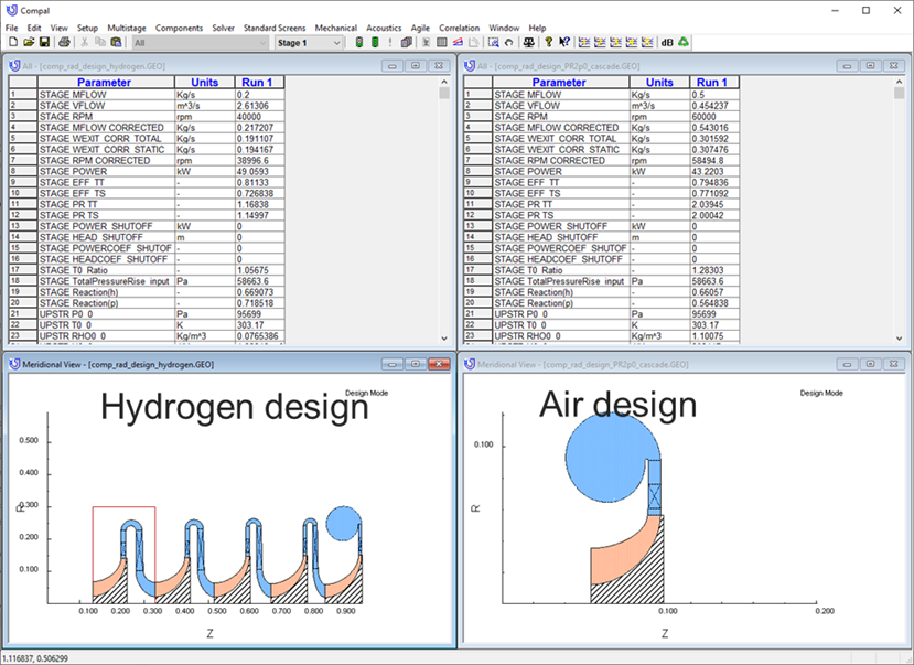
After seeing the inlet and discharge pipes shaking violently due to the instability, our customer began running numerous “what if” design cases in Concepts NREC's Agile Engineering Design System® software to find the cause and a solution . Using Concepts NREC’s PUMPAL® software, he maintained the impeller outside diameter but allowed for variables that included tip depth, blade angle distribution, and number of blades. When suitable PUMPAL cases were discovered, a single click transferred the data to AxCent® to design a replacement impeller, and the most promising designs were then analyzed for CFD with another push of a button.
The new impeller design that was chosen incorporates a conservative approach with an increased blade count and a 150 ft. NPSHR. Specific speed was reduced from 1,600 to 1,350, while suction specific speed was reduced from 11,000 to 9,000.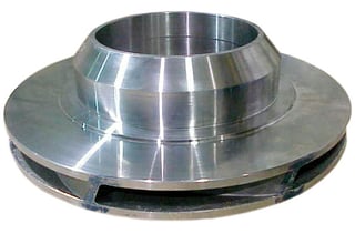
During field testing of the first reworked pump, total vibration level at the 3,900 rpm proof point was measured to be 2.0 mils to 2.2 mils, with the 10 Hz frequency contributing only 0.3 mils to 0.4 mils. At full design speed, total vibration was a low 1.4 mils to 1.5 mils. The new design also produced slightly higher output pressure, so the lowest possible running speed dropped from 3,900 rpm to 3,850 rpm.
In this case, reworking rather than replacing an existing machine was a better choice economically. It was also a good example of how Concepts NREC integrated software tools help engineers find better solutions.
Tags: CAE Software, Pumps
This post covers one of the fundamental issues that makes rotordynamics a unique subject: The Gyroscopic Effect. The gyroscopic effect can be observed in the behavior of spinning tops, fidget...
Hydrogen is attracting a lot of interest in different circles these days from: propulsion, to energy storage, to personal transportation. The most obvious benefit of hydrogen fuel is a total lack of...

Because of its promise as a non-polluting fuel, hydrogen is currently a very popular topic among the energy and turbomachinery communities. If hydrogen is reacted with pure oxygen, the thermal energy...