The Gyroscopic Effect
This post covers one of the fundamental issues that makes rotordynamics a unique subject: The Gyroscopic Effect. The gyroscopic effect can be observed in the behavior of spinning tops, fidget...


Have you ever needed to know the exact geometry of a compressor that has been running for years in your process plant? Perhaps you need to analyze how it would perform if the process fluid had to be changed to meet new government regulations. Or maybe there has been damage to the impeller and a complete mechanical analysis is required before a new one can be put into service. Eventually, everything, even well-designed turbomachinery, needs to be replaced or upgraded.
So, what do you do? CAD drawings can only provide basic dimensions and, while CAD 3D models contain all the geometric information, getting the detailed blade data into the analysis programs can be cumbersome.
Here at Concepts NREC, we get requests for reverse engineering all of the time. We not only provide that stand-alone service, but we also sell powerful software that makes this process much easier for our OEM customers that frequently run into this problem. They love that they can avoid the very time-consuming, error-prone task of transferring detailed blade data into an analysis program. This is a benefit of our integrated Agile Engineering Design System® software. It spans the entire design process, from art to part, or, in the examples above, from part to art.
Our Computer-Aided Manufacturing (CAM) software, MAX-PAC™, can import CAD models as either IGES, STEP or Parasolid files. Blade surface data, leading and trailing edges, as well as hub and blade tip contours, are defined by simply highlighting the desired surface and “collecting” the ISO curves (Figure 1a). Even when the surfaces are stitched together from several pieces, as shown (Figure 1b), we can collect these patches and generate smooth isolines (Figure 1c).
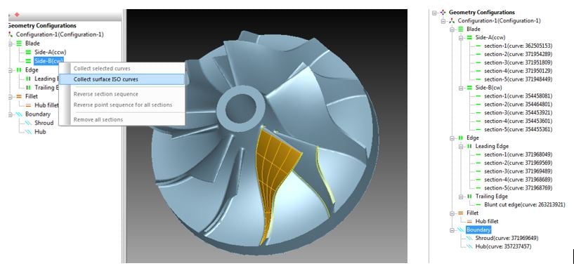
Figure 1A
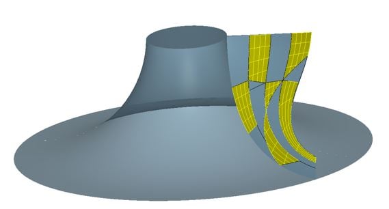
Figure 1B
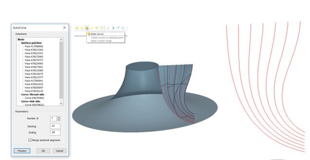
Figure 1C
Once all the data has been collected, a single click opens up the file in AxCent®, our 3D geometry software. Within MAX-PAC, the files for blading (.imp), leading and trailing edges (.edg), and hub/shroud (.bnd) are automatically created. Along each of the collected curves, blade thickness and blade angle has been calculated at each data point, thus completely defining the blading for aerodynamic analysis. The leading edge data is not included in this definition; however, AxCent supports several styles of leading edges that can be added to match the original CAD model.
Looking more closely at the thickness distribution, note that the curve fit (line) of the input data (circles) does not match well. Our software has an option to change the order of the fitting parameter equation to improve the match. This can also be done for the contours and the blade angle distribution (Figure 2).
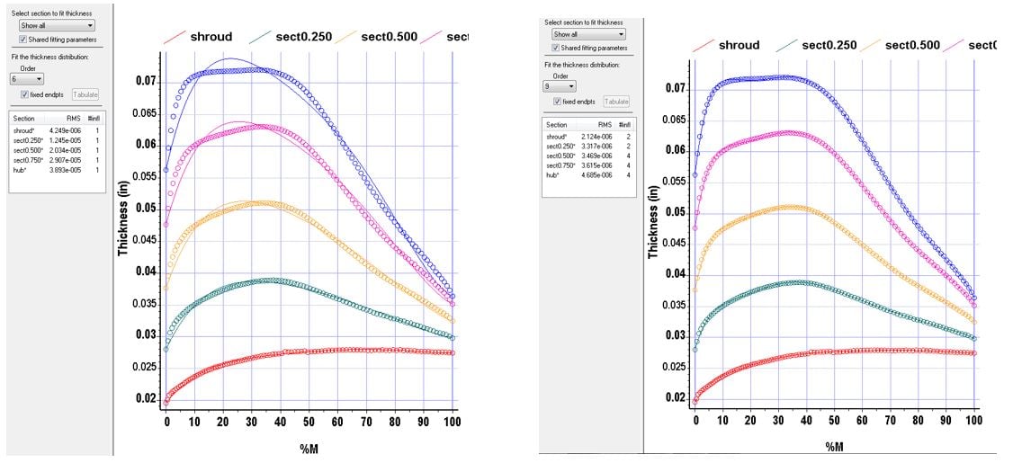
Figure 2
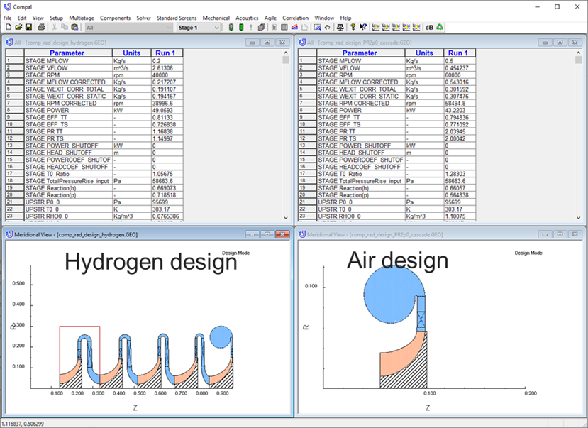
Calculating blade thickness and/or blade angle from the input x, y, z data points on the blade surfaces can lead to data points that are clearly erroneous (Figure 3). The software also has a handy feature that allows the user to manually move those data points back in line before doing the final curve fit. Entering “finish” brings the resulting geometry into AxCent. The user can then seamlessly start meanline analysis, 3D CFD analysis, or mechanical analysis. Currently, splitters must be done separately from the main blades, but by adding splitters to the original file and overlaying the splitter data, it is easy to match the splitter design intent, even if the splitter geometry differs from that of the main blades, Figure 4.
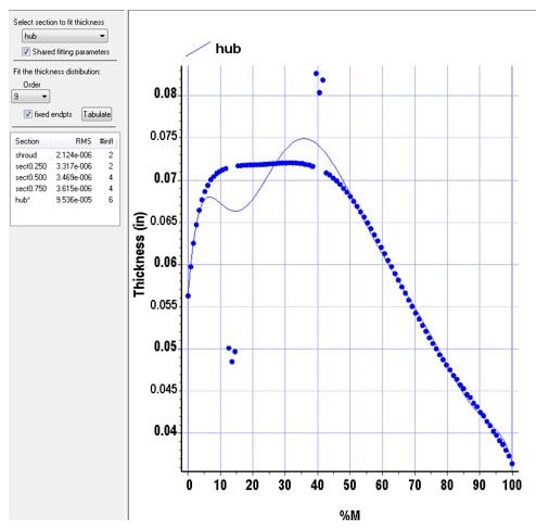
Figure 3
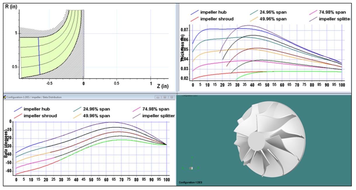
Figure 4
This process offers a cost-effective method to turn raw hardware into a usable electronic record. Once this record is in hand, it is just a few button clicks to perform other operations, such as fluid or structural analysis. It also provides a handy starting point from which to modify the shape for better performance.
OEMs and MROs servicing aging infrastructure, or acquired assets, find this process invaluable as they grapple with replacing and updating old parts that have no electronic files.
Tags: CAE Software, CAM Software, MAX-PAC, Engineering, Manufacturing
This post covers one of the fundamental issues that makes rotordynamics a unique subject: The Gyroscopic Effect. The gyroscopic effect can be observed in the behavior of spinning tops, fidget...
Hydrogen is attracting a lot of interest in different circles these days from: propulsion, to energy storage, to personal transportation. The most obvious benefit of hydrogen fuel is a total lack of...

Because of its promise as a non-polluting fuel, hydrogen is currently a very popular topic among the energy and turbomachinery communities. If hydrogen is reacted with pure oxygen, the thermal energy...