The Gyroscopic Effect
This post covers one of the fundamental issues that makes rotordynamics a unique subject: The Gyroscopic Effect. The gyroscopic effect can be observed in the behavior of spinning tops, fidget...


Computational fluid dynamic analysis (CFD) has become a standard part of the turbomachinery design process. Within Concepts NREC’s Agile Engineering Design System, FINE/Turbo, from our Partner NUMECA International, is the tool used to accomplish aerodynamic analysis of designs by applying standard methods of three-dimensional analysis. However, arriving at a converged CFD solution in any CFD program can sometimes be a challenge.
Although many things can go wrong in a CFD calculation, most solution failures can be understood within specific categories. Some solutions can be fixed with better solver settings or may require some redesigning. But before considering these options, reexamine the results of a failed CFD solution using these common reasons as the possible diagnosis for failure.
Recirculation at the solution boundary
Recirculation areas can sometimes form near the boundary of the solution domain. If this occurs, the region can grow to the point where it leaves the domain of analysis and causes significant backflow. This is one of the most common causes of CFD solution failure and most often occurs at the exit boundary, but it can also appear at the inflow plane as well. Solution failure occurs because the properties of the fluid state coming back into the solution are basically unknown, and therefore, reenter the domain poorly defined. Such a situation is called an “ill-posed” problem since the Navier- Stokes equations are a boundary condition problem and here the boundary conditions are not defined.
The effect can be caused by a sudden change in passage direction close to the exit or excessive diffusion of the flow in this region. To cure this problem, extend the domain of analysis with an accelerating flow region to fully enclose any recirculation regions, or modify the geometry to avoid separated flow near the exit boundaries. Some compromise of the actual physical geometry may be necessary.
Excessively high backpressure
When the backpressure specified in the boundary condition is too high and the momentum of the flow cannot overcome the high pressure at the exit, the solution mass flow steadily drops towards zero, the mass error explodes, and the solution soon fails. Other than lowering the exit pressure, attempted CFD calculations like these generally represent impossible flow conditions and can very rarely be forced to converge. Sometimes, restarting a high-backpressure case from a converged lower backpressure can be successful, but only at the margins of solution viability.
To cure this problem, reduce the backpressure settings in the CFD boundary conditions.
Time-step number too high
CFD solutions are inherently iterative in nature. They progress by marching forward in a time-like manner. The higher the effective time step, the faster the solution will converge. Unfortunately, high time steps can also lead to solution instability. Instability from too high a time step is most often seen early in the solution process when flow transients are at a maximum.
To cure this problem, drop the time step in the solution settings.
Bad transients
A less common cause of failure in a steady state CFD calculation is a problem with transient flow. Iterations in CFD calculations must have a rational state at each time step as it approaches convergence, otherwise the solution will fail. Obviously, these transients will depend on the initial state of the solution and the type of machine. Large, snaking, multiple blade-row passages with high Mach numbers are particularly vulnerable to bad transients.
To cure this problem, bad transients can be eliminated quite effectively with better initialization. For particularly stubborn problems, a CFD calculation can be run using the first-order scheme (first order of accuracy) and then switched to a higher order. First-order solutions are not accurate enough to quantify performance, but they are very effective for initialization.
Insufficient space after bladed elements
CFD solvers usually require a minimum amount of vaneless space between the blades and exit boundary plane. With insufficient space, the signals that come back from the boundary will not be correct and will cause the solution to fail or produce bad results.
To cure this problem, allow at least one hub-to-shroud length or one blade-to-blade length of vaneless space to exist before and after bladed segments.
Poor grid quality
Several factors affect grid quality, but grid aspect ratio and grid skewing are two of the most important. Extreme cases or just poor input can generate a bad grid. Most modern grid generators are designed to minimize grid quality problems but they do sometimes occur. In general, a finer grid is easier than a course grid to distribute properly and thus more grid points can sometimes help. If increasing the grid number is not practical, try changing the grid topology settings or overall distribution schemes for a better result.
Grid quality issues can be insidious. Even worse than solution failure, they can produce an inaccurate result that the user is unaware of.
The guidelines listed above are generally applicable to all CFD setups and solvers. Of course, every CFD solver has its own “personality”, so to speak, which can only be fully understood with experience.Tags: CAE Software, CFD
This post covers one of the fundamental issues that makes rotordynamics a unique subject: The Gyroscopic Effect. The gyroscopic effect can be observed in the behavior of spinning tops, fidget...
Hydrogen is attracting a lot of interest in different circles these days from: propulsion, to energy storage, to personal transportation. The most obvious benefit of hydrogen fuel is a total lack of...
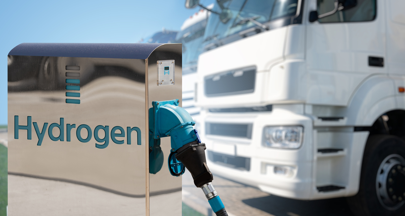
Because of its promise as a non-polluting fuel, hydrogen is currently a very popular topic among the energy and turbomachinery communities. If hydrogen is reacted with pure oxygen, the thermal energy...