The Gyroscopic Effect
This post covers one of the fundamental issues that makes rotordynamics a unique subject: The Gyroscopic Effect. The gyroscopic effect can be observed in the behavior of spinning tops, fidget...


This Blog post gives a brief outline of the throughflow method for turbomachinery flows and presents the calculated performance results of a Single-Stage Axial-Flow Compressor validation.
The throughflow method for turbomachinery performance prediction is a quasi-three dimensional CFD method that solves azimuth-averaged flow in the meridional plane. Using an azimuth-averaged approach reduces the grid resolution requirement in the tangential direction to only two points (one cell), with a corresponding reduction in the computational cost relative to a full 3-D CFD simulation. For example, for a 3-D case with 100 grid points in the tangential direction, the throughflow case will run approximately two orders-of-magnitude times faster than a corresponding 3-D CFD simulation.
Throughflow methods provide a reasonable trade-off between speed and accuracy and are useful for performing parametric-studies early in the conceptual and preliminary design phases [1]. An integrated throughflow solver is incorporated in the Concepts NREC’s Agile Engineering Design System®.
Easy Access to Throughflow Solver Loss Models
In lieu of resolving the tangential flow direction, throughflow solvers use body-force source terms to capture blade profile losses and turning effects and shock losses. The loss models are derived primarily from the Koch-Smith model for compressors and the Ainley-Mathieson model for turbines.
The Concepts NREC’s Agile Engineering Design System® provides access to an integrated throughflow solver (grid generation, pre-processing, post-processing, etc.) and it provides options for different loss and deviation models, Figure 1. The built-in throughflow solver also provides a set of default settings. These losses and settings can be calibrated to match actual performance data.
The accuracy and utility of the methodology was indicated by performing a set of throughflow validation cases [1].
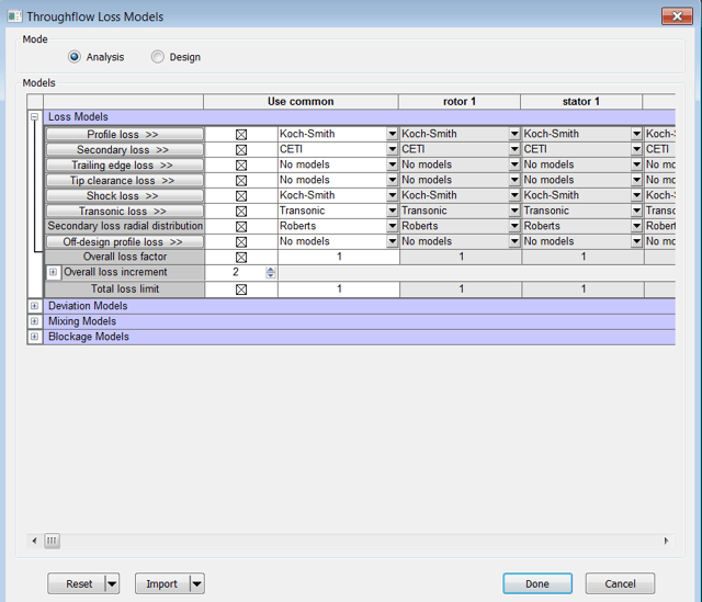
Figure 1: Some of the options for Through-Flow Loss Models
Overview of GT2015-43763 Validation Cases
Reference [1] presents a set of validation cases. These cases include: NACA cascade loss-bucket calculations (loss-coefficient versus incidence angle); DCA cascade loss-bucket calculations; performance map calculations for the DFLVR Single-Stage Axial-Flow Compressor and a study of the Cambridge Low-Speed Turbine.
The DFLVR Single-Stage Axial-Flow Compressor is a high-speed compressor tested in Germany in the 1970s. The compressor produces a pressure ratio of 1.51 while operating at a relative tip Mach number of 1.4 at the design point. Results for this case were presented in 2015 [1] and are repeated here.
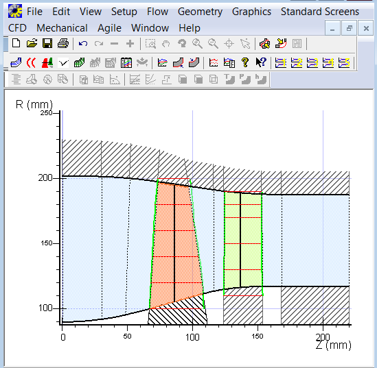
Figure 2: Meridional View of DFLVR Single-Stage Axial Compressor Throughflow Model
The compressor meridional view is shown in Figure 2 and was generated by the throughflow solver pre-processor. A set of throughflow Single-Stage Axial-Flow Compressor validation runs was built by accepting the default parameters for the loss models and running 55%, 85%, and 100% speed-lines. At least nine throughflow cases were run for each speed. The efficiency and pressure-ratio results are compared to experimental data and 3-D CFD results in Figure 3.
Reference [1] concluded that the throughflow solver did quite well in capturing the magnitude and characteristic losses in the stage for the DFLVR Single-Stage Axial Compressor. They also noted that the low-speed line is somewhat higher in performance relative to the test performance values.

Figure 3: Predicted Performance using Default Models/Settings, Reference [1]
Remarks
The throughflow solver is fast and allows easy access to loss model settings and parameters via a graphical user interface window. Algorithm updates/settings that build on the improvements presented in [1] are being considered.
References
[1] Andersen, M. and Bonhaus, D.L., "A Comprehensive Throughflow Solver Method for Modern Turbomachinery Design," ASME Turbo Expo 2015, GT2015-43763, June 15-19, 2015, Montreal, Canada.
Tags: CAE Software
This post covers one of the fundamental issues that makes rotordynamics a unique subject: The Gyroscopic Effect. The gyroscopic effect can be observed in the behavior of spinning tops, fidget...
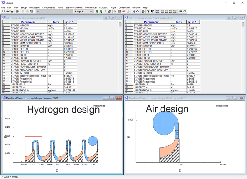
Hydrogen is attracting a lot of interest in different circles these days from: propulsion, to energy storage, to personal transportation. The most obvious benefit of hydrogen fuel is a total lack of...

Because of its promise as a non-polluting fuel, hydrogen is currently a very popular topic among the energy and turbomachinery communities. If hydrogen is reacted with pure oxygen, the thermal energy...