The Gyroscopic Effect
This post covers one of the fundamental issues that makes rotordynamics a unique subject: The Gyroscopic Effect. The gyroscopic effect can be observed in the behavior of spinning tops, fidget...


Structural vibration is a natural phenomenon exhibited by all structures, by virtue of simply possessing mass and having an associated structural stiffness. Thus, any structure or assembly of structures, with a mass attribution, will possess some structural stiffness. This stiffness will characterize the vibrational response of the structure, depending on the type of boundary conditions constraining the structure. For complex structural configurations, this vibrational response can be determined by numerical techniques, such as the finite element method, which allows calculation of the natural frequencies of vibration of the structure and the respective mode shapes of vibration associated with each of these natural frequencies.
Structural vibration is a natural phenomenon exhibited by all structures, by virtue of simply possessing mass and having an associated structural stiffness. Thus, any structure or assembly of structures, with a mass attribution, will possess some structural stiffness. This stiffness will characterize the vibrational response of the structure, depending on the type of boundary conditions constraining the structure. For complex structural configurations, this vibrational response can be determined by numerical techniques, such as the finite element method, which allows calculation of the natural frequencies of vibration of the structure and the respective mode shapes of vibration associated with each of these natural frequencies.
In the mechanical design of turbomachinery, it is critical to determine the natural frequencies of vibration—of individual components such as radial and axial compressors and turbines using finite element analysis in a software package such as pbFEA, as well as the complete rotor assembly via rotordynamic analysis in a software package such as DyRoBeS. The mechanical design process then intersects the aerodynamic design process of the turbomachine and seeks to avoid any running operation at or near these natural frequencies within a certain error margin, which is typically a best design practice. This is critical to avoid potential excitation of any of the natural modes of vibration, because this can lead to resonance, and ultimately, high-cycle fatigue failure of the machine or assembly.
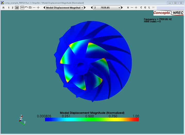
The vibrational modes for radial turbomachines are generally identifiable through two major forms of shape: those in which only the blade vibrational behavior is dominant, and those in which the impeller or rotor disc also participates in vibration. A pbFEA computation of the primary-blade flapping mode of a typical turbochargercentrifugal compressor is shown in the figure below. Blade mode shapes that exhibit high-order, complex behavior are more difficult to excite than primary blade-flapping or second-order, blade-bending modes, in that they require much higher excitation energy from the driving source, and hence pose less risk or concern of high-cycle fatigue failure. The running speeds corresponding to disc modal frequencies, however, are completely avoided, since disk failure modes tend to be significantly more destructive than blade failure modes.
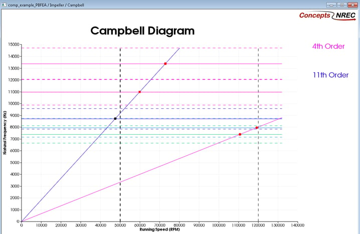
As best practice, it is sought, through mechanical design, to have all blade and disc vibrational modal frequencies of the turbomachine to be above 4x that of the running passing excitation frequency of the turbomachine, with a 10% computational error margin. Additionally, fundamental blade and all disc modal frequencies lying at multiples of synchronous passing excitation frequencies that correspond to any upstream or downstream stator components are also avoided; this means that any radial turbomachine designed, for example, with 6 inlet guide vanes, must not have a primary or secondary blade modal frequency, or any disc modal frequency, within 10% error margin of the 6x running passing excitation frequency of the turbomachine. The pbFEA software will automatically create a Campbell (shown below) and/or interference diagram(s) so that an analyst can ensure that this is achieved, and through these mechanical design procedures, high-cycle fatigue failure of turbomachines is avoided.
Tags: Engineering
This post covers one of the fundamental issues that makes rotordynamics a unique subject: The Gyroscopic Effect. The gyroscopic effect can be observed in the behavior of spinning tops, fidget...

The United States is returning to the moon – to stay – and the team at Concepts NREC is helping them get there.

Artificial Intelligence (AI) uses algorithms and machine learning techniques to analyze and evaluate a research topic, making it fast and easy, while research going through peer review is rigorously...