The testing of turboshaft engines is necessary to ensure that post-repair performance meets or exceeds requirements for safe aircraft operation. Testing typically involves several phases such as: seal break-in; transient response; performance check and control system validation. Dynamometers are used to simulate the load imposed during operation during testing.
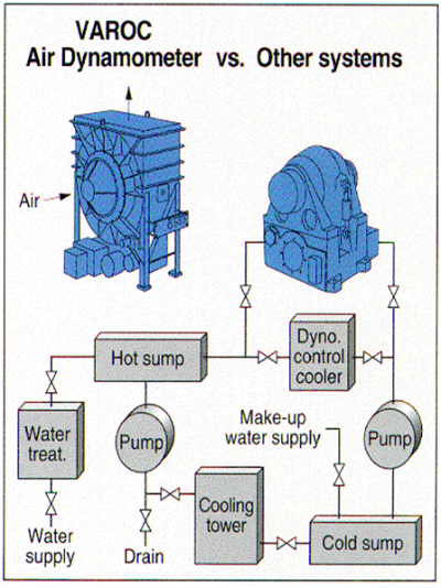
High-speed hydraulic dynamometers, known as water brakes, have been used for decades to test turboshaft engines. They are large, complex machines that flow huge volumes of water through a casing containing a rotor spun by the turboshaft engine. The rotors are normally multi-staged and transfer energy to the water, which causes the temperature of the water to rise. Hydraulic dynamometers tend to be designed for narrow engine HP applications so the flow of water is proportional to the power it absorbs because overheating would damage the dynamometer.
Over the years, limitations of water brakes have been well documented:
- They require large water tanks, cooling systems and water treatment systems, making them expensive and difficult to deploy in certain climates.
- High level of monitoring and maintenance are required to ensure precise water volume and quality to avoid damaging the expensive dynamometer.
- Bearing lubrication issues are common because water lubrication schemes are intolerant of particulate matter and oil-based lubrication requires highly effective seals that are also susceptible to water-quality-related failures.
Beyond the extensive infrastructure and high level of maintenance, hydraulic dynamometers also suffer from cavitation. Cavitation occurs when the local water pressure equals the vapor pressure of water. As the dynamometer rotor spins in water, high shear forces transfer energy to the water. Locally, this energy transfer can be so large that the water effectively boils, producing a cavitation bubble. As these bubbles collapse, shock waves can quickly cause catastrophic damage to the dynamometer rotors. Poor design, inappropriate operation, or a system fault can all produce dangerous cavitation that can quickly destroy machinery.
One way to help avoid cavitation is a clean, reliable water supply. Consequently, hydraulic dynamometer water supply systems must be designed with fail-safe and back-up features, increasing their cost and complexity. Failing to ensure a clean reliable water supply can lead to, engine overspeed or dynamic instability of the dynamometer. This will prevent the hydraulic dynamometer from performing transient engine tests adequately.
Despite efforts to monitor vibration and water quality, the onset of cavitation can go undetected, resulting in catastrophic damage very quickly. And, given the fact that hydraulic dynamometers tend to be tailor designed, replacement parts usually must be fabricated, resulting in excessive downtime.
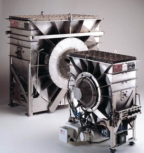
An alternative to hydraulic dynamometers is the air dynamometer. An air dynamometer uses airfoils on a spinning rotor to transfer energy to the air. Water is not required, which eliminates the need for extensive and expensive support systems as well as bearing seal and all cavitation concerns. 
Concepts NREC manufactures the patented VAROC air dynamometer at its headquarters in Vermont. The VAROC air dynamometer is throttled using shrouds that cover the rotating airfoils. This feature allows just two air dynamometer designs to absorb power from 50 HP to 18,000 HP. Consequently, parts can be stocked, eliminating manufacturing lead times and testing downtime.

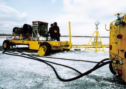
Militaries around the world have relied upon air dynamometers for decades. This proven technology has been deployed to some of the toughest environments on earth to help ensure the safety and integrity of the military’s turboshaft aircraft.

Concepts NREC is introducing a commercial air dynamometer in 2017, intended for stationary testing applications that require worry-free, reliable turboshaft testing without the hassles associated with water systems. Contact us to learn more.


