Design Software Solution for Industrial Pumps

The Concepts NREC Agile for Industrial Pumps bundle delivers an integrated tool chain for the entire component design workflow of industrial pumps. Starting with a wizard-based 1D design and analysis in PUMPAL®, the designer will be quickly guided to a flow path that meets their specifications. This will result in a machine that has appropriate sizing, number of stages, and initial performance predictions. From there, more detailed analysis may be employed to ascertain the feasibility of the machine by leveraging such tools as multi-point analysis to create performance maps.
The Agile link is used to seamlessly transfer all data from PUMPAL® to our flagship 3D design product AxCent®. This is where the designer can refine the design by modifying distributions such as beta angle, lean, blade thickness, and many other geometric design parameters accompanied by real time updates of the 3D geometry. These changes can be moved forward into 3D CFD preparation or the Agile link may be used to return to PUMPAL® and determine the impact of the 3D geometry parameterization on the 1D analysis.
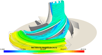
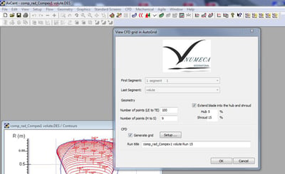
All pre-processing for 3D CFD is completed using TurboLink™. Here, the designer can provide all grid parameters, loads, and boundary conditions with the convenience of never leaving the AxCent® interface. The fully prepared analysis is then initiated, while still in the AxCent® interface, and all numerical calculations are completed using Cadence OMNIS/Turbo CFD. Upon completion, the results of the numerical solution are returned to TurboLink™ and all turbomachinery-specific post-processing is completed within the AxCent® interface.


