Why Meanline Scripting is Becoming Essential for Turbomachinery Design
Manual meanline design can sometimes feel less like design and more like managing a chain of tiny decisions.


This post covers one of the fundamental issues that makes rotordynamics a unique subject: The Gyroscopic Effect.
The gyroscopic effect can be observed in the behavior of spinning tops, fidget spinners, inertial navigation systems, and many types of turbomachinery. If you have ever tried to tilt an object while it is spinning, then you may have noticed this effect.
When engineers are designing rotating machinery, they will often need to perform a rotordynamics analysis to predict the lateral vibration modes of the rotating components. If these lateral vibration modes are excited during operation, there is a potential for the machine to begin vibrating at unacceptably high levels. This high level of vibration can lead to poor machine performance and potential damage. In order to accurately predict the lateral vibration modes of a rotating system, it is often essential that the gyroscopic effect is accounted for in a rotordynamics analysis.
To help illustrate this concept, a simple rotor model has been constructed using the ARMD software. This model consists of a solid shaft with a large overhung component at one end.
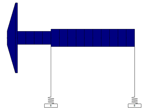
Figure 1: ARMD Software Model for Lateral Analysis
This model can be used to determine the natural frequencies of lateral vibration. When the rotor is spinning (shaft direction of rotation is clockwise in the below illustration) at a low speed, say 10,000 rpm, the first four natural frequencies are: 16,686 rpm, 20,050 rpm 60,255 rpm, and 67,859 rpm. It is also worth noting that the 1st and 3rd modes are reverse precision modes, where the whirling motion of the rotor is in the direction opposite of rotation (illustrated below with counter-clockwise orbit directions). The 2nd and 4th modes are forward precession modes, where the whirling motion is in the same direction as rotation.
| Mode 1 | Mode 2 |
 |
 |
| Mode 3 | Mode 4 |
 |
 |
To demonstrate how the gyroscopic effect will influence these modes, we can repeat the analysis for a scenario where the rotational speed is much higher, say 50,000 rpm. A comparison table is shown below, with the first four lateral vibration modes for these two scenarios:
Table 1: Lateral Modes for Two Rotational Speeds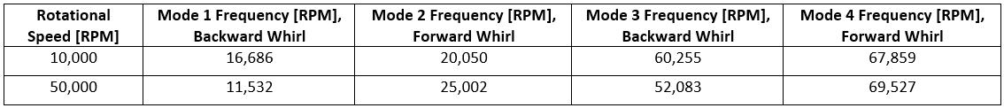
From the summary table above, we can make a few interesting observations:
All three of these observations are due to the gyroscopic effect and are typical for many types of rotating machines. What if we wanted to study how the frequencies of these modes will change over a wide range of operating speeds, and we wanted to know when the rotational speed will be equal to these natural frequencies? It turns out there is a type of plot that expresses this information, and it is commonly used in many industries to help identify the risk of exciting a critical speed.
In the figure below, we have plotted the natural frequencies on the vertical axis, and the rotational speed of the rotor on the horizontal axis. The upward sloping black dashed line represents the rotational speed of the rotor. There is a lot more that we could say about this type of chart, but we will leave that for another day.
.png?width=1044&height=596&name=Figure2%20Gresham%20(002).png)
Figure 2: Lateral Natural Frequencies Plotted Against Rotational Speed
In conclusion, the dynamic behavior of a rotating system can be influenced by the gyroscopic effect, and we have used a simple example to explore this phenomenon. Because the gyroscopic effect is a consequence of the conservation of angular momentum, it is important to consider when you are dealing with objects that spin fast and have large inertia.
We welcome your questions and comments here or contact us at info@conceptsnrec.com.
Tags: CAE Software, Engineering, Rotordynamics

Manual meanline design can sometimes feel less like design and more like managing a chain of tiny decisions.

For most turbomachinery engineers, optimization isn’t a new idea. It’s a critical part of their workflow that can’t be overlooked. But sometimes that crucial step isn’t easy to get to.
It’s no secret that turbomachinery design has been one of the most demanding CAE environments, thanks to tight tolerances, complex physics, and long design cycles. That hasn’t changed in 2026, but...