%20and%20Applied%20Relative%20Total%20Temperatures%20to%20FEM%20(right).jpg?width=600&name=FEM%20of%20Radial%20Turbine%20(left)%20and%20Applied%20Relative%20Total%20Temperatures%20to%20FEM%20(right).jpg)
FEM of Radial Turbine (left) and Applied Relative Total Temperatures to FEM (right)
Aero Load Mapping
This feature enables users to automatically link the CFD results to the structural finite element model (FEM). As a result, the static pressures, relative total temperatures, and the heat-transfer coefficients are automatically mapped to all of the flow path surfaces in the FEM.
In addition to the automated mapping, the user can apply any pressure, temperature, or heat-transfer coefficient distribution to the non-flow path surfaces (secondary flow paths) such as the nose, bore, or backface.
Designing turbomachinery is an inherently iterative process. The ability to update aero loading on an FEM with only a few “mouse clicks” within a robust design environment eliminates the need to move back and forth between CAD, analysis software and the design software. With Concepts NREC's solution, it is all encapsulated into one closed loop.
The benefits of Pushbutton FEA Aero Load Mapping are:
- Increasing the accuracy of the structural simulations and stress predictions your mechanical/structural engineers produce.
- Reducing the time required for the overall design process by many hours or even days.
- Enables more iterations, within a given design time, to achieve improved performance/durability balance.
-
This feature enables users to automatically link the CFD results to the structural finite element model (FEM). As a result, the static pressures, relative total temperatures, and the heat-transfer coefficients are automatically mapped to all of the flow path surfaces in the FEM.
In addition to the automated mapping, the user can apply any pressure, temperature, or heat-transfer coefficient distribution to the non-flow path surfaces (secondary flow paths) such as the nose, bore, or backface.
Designing turbomachinery is an inherently iterative process. The ability to update aero loading on an FEM with only a few “mouse clicks” within a robust design environment eliminates the need to move back and forth between CAD, analysis software and the design software. With Concepts NREC's solution, it is all encapsulated into one closed loop.
The benefits of Pushbutton FEA Aero Load Mapping are:
- Increasing the accuracy of the structural simulations and stress predictions your mechanical/structural engineers produce.
- Reducing the time required for the overall design process by many hours or even days.
- Enables more iterations, within a given design time, to achieve improved performance/durability balance.
%20and%20Applied%20Relative%20Total%20Temperatures%20to%20FEM%20(right).jpg?width=1255&name=FEM%20of%20Radial%20Turbine%20(left)%20and%20Applied%20Relative%20Total%20Temperatures%20to%20FEM%20(right).jpg)
FEM of Radial Turbine (left) and Applied Relative Total Temperatures to FEM (right)
-
An Interference Diagram is a qualitative analysis tool that relates a components natural frequencies to operating speeds, sources of external excitation, and mode shapes. This is an automated post-processing feature of PushButton FEA performed after completing a cyclic symmetry modal analysis (EIGEN value extraction analysis).
Interference Diagrams highlight potential problem frequencies and provide guidance on how to avoid these frequencies early in the design process - avoiding costly and time-consuming redesign work.
Using an Interference Diagram also breaks down historical design barriers related to rotating and stationary blade counts and unleashes a broader range of design possibilities.
The biggest benefit of this powerful tool is the ability to design early on around known excitations in the system, thereby lowering the risk of (avoiding) vibratory failure, fractures, and high-cycle fatigue.
-
Both quadratic and linear elements are available for all analysis types. Thermal, static, and modal solvers are available. Cut faces can be modeled using both cyclic and coupled DOF boundary conditions. All of the load information is created from the previously calculated aerodynamic conditions using rapid load, MST or CFD. These aerodynamic loads are applied to the FEA model elements as convective heat transfers and pressures applied to the external element faces. Thermal stresses can be included in the static analysis, and the static stresses can also be incorporated as a pre-stress condition for the modal solver. Spin or centrifugal softening is available, as is the use of a lumped mass matrix instead of the default consistent mass matrix.
-
There are no files involved in the transfer of information from the aero to the mechanical design, so modifications to the aero definitions are immediately updated into the mechanical design. This reduces the likelihood of the two processes becoming desynchronized due to outdated definition files.
-
In addition to the integrated Pushbutton FEA solver, the software maintains its links with other FEA solvers such as ANSYS®, COSMOS/M®, NASTRAN™ and ABAQUS® and therefore can also be utilized with your existing tools. Using a 3rd party solver means that Pushbutton FEA becomes a powerful and intuitive geometry design tool with grid generation. Some post-processing capability is also available, such as Goodman, Campbell, and interference diagrams.
-
For the Concepts NREC Pushbutton FEA solver, full 3D post-processing is available. Displaced geometry color surface contour plots of temperature, displacement, and stresses can be overlaid with undisplaced wireframes, making it easier to visualize the effects of the load conditions. There is also modal displacement-based animation which can be used to view the mode shapes. This is particularly useful for visualizing the typical modal displaced shapes.
This feature enables users to automatically link the CFD results to the structural finite element model (FEM). As a result, the static pressures, relative total temperatures, and the heat-transfer coefficients are automatically mapped to all of the flow path surfaces in the FEM.
In addition to the automated mapping, the user can apply any pressure, temperature, or heat-transfer coefficient distribution to the non-flow path surfaces (secondary flow paths) such as the nose, bore, or backface.
Designing turbomachinery is an inherently iterative process. The ability to update aero loading on an FEM with only a few “mouse clicks” within a robust design environment eliminates the need to move back and forth between CAD, analysis software and the design software. With Concepts NREC's solution, it is all encapsulated into one closed loop.
The benefits of Pushbutton FEA Aero Load Mapping are:
- Increasing the accuracy of the structural simulations and stress predictions your mechanical/structural engineers produce.
- Reducing the time required for the overall design process by many hours or even days.
- Enables more iterations, within a given design time, to achieve improved performance/durability balance.
FEM of Radial Turbine (left) and Applied Relative Total Temperatures to FEM (right)
An Interference Diagram is a qualitative analysis tool that relates a components natural frequencies to operating speeds, sources of external excitation, and mode shapes. This is an automated post-processing feature of PushButton FEA performed after completing a cyclic symmetry modal analysis (EIGEN value extraction analysis).
Interference Diagrams highlight potential problem frequencies and provide guidance on how to avoid these frequencies early in the design process - avoiding costly and time-consuming redesign work.
Using an Interference Diagram also breaks down historical design barriers related to rotating and stationary blade counts and unleashes a broader range of design possibilities.
The biggest benefit of this powerful tool is the ability to design early on around known excitations in the system, thereby lowering the risk of (avoiding) vibratory failure, fractures, and high-cycle fatigue.
Both quadratic and linear elements are available for all analysis types. Thermal, static, and modal solvers are available. Cut faces can be modeled using both cyclic and coupled DOF boundary conditions. All of the load information is created from the previously calculated aerodynamic conditions using rapid load, MST or CFD. These aerodynamic loads are applied to the FEA model elements as convective heat transfers and pressures applied to the external element faces. Thermal stresses can be included in the static analysis, and the static stresses can also be incorporated as a pre-stress condition for the modal solver. Spin or centrifugal softening is available, as is the use of a lumped mass matrix instead of the default consistent mass matrix.
There are no files involved in the transfer of information from the aero to the mechanical design, so modifications to the aero definitions are immediately updated into the mechanical design. This reduces the likelihood of the two processes becoming desynchronized due to outdated definition files.
In addition to the integrated Pushbutton FEA solver, the software maintains its links with other FEA solvers such as ANSYS®, COSMOS/M®, NASTRAN™ and ABAQUS® and therefore can also be utilized with your existing tools. Using a 3rd party solver means that Pushbutton FEA becomes a powerful and intuitive geometry design tool with grid generation. Some post-processing capability is also available, such as Goodman, Campbell, and interference diagrams.
For the Concepts NREC Pushbutton FEA solver, full 3D post-processing is available. Displaced geometry color surface contour plots of temperature, displacement, and stresses can be overlaid with undisplaced wireframes, making it easier to visualize the effects of the load conditions. There is also modal displacement-based animation which can be used to view the mode shapes. This is particularly useful for visualizing the typical modal displaced shapes.
Aero Load Mapping
his feature enables users to automatically link the CFD results to the structural finite element model (FEM). As a result, the static pressures, relative total temperatures, and the heat-transfer coefficients are automatically mapped to all of the flow path surfaces in the FEM.
In addition to the automated mapping, the user can apply any pressure, temperature, or heat-transfer coefficient distribution to the non-flow path surfaces (secondary flow paths) such as the nose, bore, or backface.
Designing turbomachinery is an inherently iterative process. The ability to update aero loading on an FEM with only a few “mouse clicks” within a robust design environment eliminates the need to move back and forth between CAD, analysis software and the design software. With Concepts NREC's solution, it is all encapsulated into one closed loop.
The benefits of Pushbutton FEA Aero Load Mapping are:
- Increasing the accuracy of the structural simulations and stress predictions your mechanical/structural engineers produce.
- Reducing the time required for the overall design process by many hours or even days.
- Enables more iterations, within a given design time, to achieve improved performance/durability balance.
FEM of Radial Turbine (left) and Applied Relative Total Temperatures to FEM (right)
Interference Diagrams
An Interference Diagram is a qualitative analysis tool that relates a components natural frequencies to operating speeds, sources of external excitation, and mode shapes. This is an automated post-processing feature of PushButton FEA performed after completing a cyclic symmetry modal analysis (EIGEN value extraction analysis).
Interference Diagrams highlight potential problem frequencies and provide guidance on how to avoid these frequencies early in the design process - avoiding costly and time-consuming redesign work.
Using an Interference Diagram also breaks down historical design barriers related to rotating and stationary blade counts and unleashes a broader range of design possibilities.
The biggest benefit of this powerful tool is the ability to design early on around known excitations in the system, thereby lowering the risk of (avoiding) vibratory failure, fractures, and high-cycle fatigue.
FEA Solver
Both quadratic and linear elements are available for all analysis types. Thermal, static, and modal solvers are available. Cut faces can be modeled using both cyclic and coupled DOF boundary conditions. All of the load information is created from the previously calculated aerodynamic conditions using rapid load, MST or CFD. These aerodynamic loads are applied to the FEA model elements as convective heat transfers and pressures applied to the external element faces. Thermal stresses can be included in the static analysis, and the static stresses can also be incorporated as a pre-stress condition for the modal solver. Spin or centrifugal softening is available, as is the use of a lumped mass matrix instead of the default consistent mass matrix.
Closely Coupled Aero & Mechanical
There are no files involved in the transfer of information from the aero to the mechanical design, so modifications to the aero definitions are immediately updated into the mechanical design. This reduces the likelihood of the two processes becoming desynchronized due to outdated definition files.
Support of Other Solvers
In addition to the integrated Pushbutton FEA solver, the software maintains its links with other FEA solvers such as ANSYS®, COSMOS/M®, NASTRAN™ and ABAQUS® and therefore can also be utilized with your existing tools. Using a 3rd party solver means that Pushbutton FEA becomes a powerful and intuitive geometry design tool with grid generation. Some post-processing capability is also available, such as Goodman, Campbell, and interference diagrams.
Post-Processing
For the Concepts NREC Pushbutton FEA solver, full 3D post-processing is available. Displaced geometry color surface contour plots of temperature, displacement, and stresses can be overlaid with undisplaced wireframes, making it easier to visualize the effects of the load conditions. There is also modal displacement-based animation which can be used to view the mode shapes. This is particularly useful for visualizing the typical modal displaced shapes.
Product Support

Customer-driven Improvement

Technical Support

Documentation
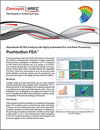
pbFEA Brochure
Pushbutton FEA™ enables aerodynamic and structural design to be performed concurrently within AxCent® utilizing the integrated
FEA tools.