What is a Consortium, and Why Would You Join One?
Merriam-Webster’s definition is, “an agreement, combination, or group (as of companies) formed to undertake an enterprise beyond the resources of any one member.” The word is Latin, derived from...


Perhaps the most common type of diffuser in turbomachinery is the conical diffuser. This diffuser is found at the exit of every volute as the geometry transitions to the exit flange. This conical diffuser must be sized appropriately to maximize machine performance across the desired flow range and can have a large impact on the end footprint and performance of the turbomachine.
Diffuser design can be difficult, and it is helpful to be guided by test data. The use of the data gives the designer a road map to geometry and decisions that will help maximize the performance of the turbomachine. A diffuser map is generated from the collection of test data from numerous diffusers with varying conditions compiled into a useful form for use in design and analysis.
A compilation of such conical diffuser maps is provided in Diffuser Design Technology, a comprehensive review of diffuser technology. This resource has diffuser maps for channel diffusers, conical diffusers, annular diffusers and vaneless diffusers with references about the data to ensure the designer understands limitations of its use. The conical diffuser maps are organized according to inlet aerodynamic blockage, Mach number, and Reynolds number. An example of a conical diffuser map is shown below for low inlet Mach number, low inlet Reynold number, and low inlet aerodynamic blockage.
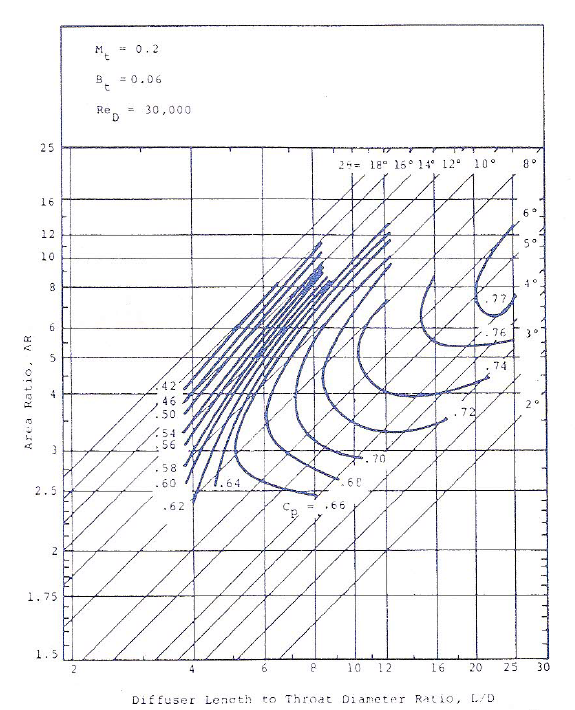
Conical diffuser performance map for low inlet Mach number, low inlet Reynold number, and low inlet aerodynamic blockage from Diffuser Design Technology
The diffuser map shows contours of a pressure recovery coefficient (Cp) for various combinations of area ratio (AR) and length over inlet hydraulic diameter (L/D). The ratio of the exit flange area to the volute throat area sets the area ratio of the conical diffuser. From this quantity, a suitable length can be determined, based on the throat hydraulic diameter. The pressure recovery values shown in the map may not match the actual pressure recovery in each application. The level of pressure recovery will be shifted by additional factors specific to each application, such as the impact of inlet swirl, inlet flow distortion, wall contouring, etc. Many design decisions may impact the final pressure recovery in the diffuser.
There are usually a couple of geometric quantities that are known when beginning a design of a conical diffuser, such as the volute throat area (which sets capacity) and the exit flange diameter. It could also be that there is a fixed or maximum length that is available to meet the exit flange.
Given the known geometric quantities, and the appropriate conical diffuser map, one can begin to lay out the expected size and initial estimate of performance. For example, in the map above, a conical diffuser with an area ratio of 3 would have a pressure recovery coefficient near 0.67 with an L/D of 6.
It is conceivable that there is a large diffuser area ratio specified by a required exit flange size that necessitates a longer diffuser than will fit within the geometric envelope available. If a diffuser is used that does not have sufficient length for the given area ratio, the diffuser will stall and, at minimum, reduce machine performance. To correct this, additional diffusion will need to take place before the volute. This is accomplished through the addition of a diffusing element to the flow path after the impeller. This will reduce velocities in the flow downstream and increase the size of the volute throat. The larger volute throat will reduce the conical diffuser area ratio to the fixed flange size and reduce the required length of the conical diffuser with an acceptable performance level. After the initial layout of the diffuser has been made, the performance should be verified with appropriate Computational Fluid Dynamics (CFD) analyses and, when suitable, proper testing of the machine.
In some instances, the design of the conical diffuser may be simple and straightforward while others will require many iterations to fit the diffuser into the required geometric envelope while meeting performance goals. Whatever level of difficulty in conical diffuser design diffuser performance maps allow for design decisions to be anchored to sound data to maximize project success and reaching maximum machine performance.
Tags: Diffusers, Engineering

Merriam-Webster’s definition is, “an agreement, combination, or group (as of companies) formed to undertake an enterprise beyond the resources of any one member.” The word is Latin, derived from...