Achieving optimum performance and efficiency in a gas turbine engine requires pushing operating temperatures as high as possible. In fact, many gas turbine engines in service today operate at hot-gas temperatures which are much greater than the incipient melting point of typical turbine airfoil base alloys. Successful operation in this extreme gas temperature environment requires turbine airfoils be designed using special high-temperature alloys, metallic and ceramic coatings, and complex cooling configurations.
Turbine airfoil cooling configurations utilize conduction, forced convection, and film cooling techniques to achieve acceptable metal temperature levels. Many different cooling features are utilized in these airfoil designs, including channels (with and without turbulators), multi-pass serpentines, pedestals, impingement ribs, impingement tube inserts, axial ribs, and trailing edge exit slots.
Film cooling patterns are defined using both round and shaped cooling holes, each with its own unique film effectiveness characteristics. Combining these design options into the best possible cooling configuration has always been a challenge.
Concepts NREC offers the Cooled Turbine Airfoil Agile Design System or CTAADS™. CTAADS is a systematic, comprehensive and rapid 3D modeling software tool for designing cooling configurations for both axial turbine vanes and blades. Starting with an imported external airfoil shape, CTAADS constructs a 3D solid model of the cored turbine airfoil based on detailed fixed and parametric inputs which define the cooling configuration. This model can be reviewed in CTAADS or exported to a third party CAD package. CTAADS also performs a complete 3D, steady-state, thermal analysis using a finite element model built from the solid model. Utilizing imported CFD analysis results, CTAADS predicts both external and internal boundary conditions and automatically maps the results to the 3D finite element model. The external boundary conditions are calculated using STAN7; internal boundary conditions use a modified version of the 1D fluid network solver, GFSSP. The internal fluid network is built from resistance models which define the heat transfer and pressure loss characteristics of various cooling features, but CTAADS allows for customization with a user’s own correlations.
CTAADS utilizes the classic definition for film cooling, where users enter their film effectiveness curves for each cooling hole type. The 3D finite element model thermal analysis is solved with the Thermal Analysis System (TAS). After constructing the thermal and boundary conditions models, CTAADS automatically iterates through each software module in sequence until a fully converged solution is attained and available for post-processing.
In the past couple of years, CTAADS has undergone numerous improvements to provide more options and better usability for the designer. The upgrades can be divided into three main categories:
- Expanded Cooling Configuration Options
- Refined Modeling Techniques
- Improved Pre/Post- Processing Capabilities
These enhancements increase designer productivity and reduce the time and cost to define the best possible cooling configuration.
Cooling Configuration Options
Several new cooling configuration options will increase the range of turbine airfoil cooling designs that can be modeled in CTAADS.
- Two new trailing edge configurations include a solid trailing edge and a trailing edge exit slot only design. The solid trailing edge option can model both simple radial cooling configurations without active trailing edge cooling or designs that utilize a cooling hole row positioned near the trailing edge. Designs with trailing edge exit slots connected directly to the aft main core passage are more common in very small gas turbine airfoils where miniaturized cooling configurations are required.
- CTAADS can now model cooling air resupply holes for multi-pass serpentine designs, which are used to minimize overall cooling airflow rates by tailoring airflow to regions with the highest external heat load.
- Another significant upgrade allows for many common cooling features to be defined with variable axial length in the radial direction. Geometry such as leading edge and trailing edge impingement cavities, trailing edge exit slots, and pressure side cut-backs are no longer restricted to a constant axial length, providing more flexibility for airfoil shapes that vary radically in the radial direction, including substantial changes in mean camber length.
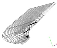 Cooling Configuration Examples — Variable Length LE Impingement Cavity; Solid Trailing Edge
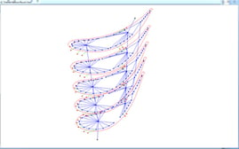
Examples of 1D Fluid Network Schematic — Double Impingement Tube Vane
Modeling Techniques
Thermal model accuracy is critical in defining the most efficient and producible cooling configuration to meet design life requirements. Local hot spots or relatively small changes in blade section average temperature can have a dramatic impact on airfoil durability. In order to improve predicted results, many refinements have been made to CTAADS boundary conditions and thermal modeling techniques. These upgrades span all aspects of the thermal analysis, including unique options such as user-defined “Products of Combustion” gas properties. All the new CTAADS boundary conditions and thermal modeling refinements will reduce analysis time and improve the thermal results.
- One new option ensures that free-stream conditions from just outside the Navier-Stokes CFD-predicted boundary layer are captured for use by STAN7. This option resolves free-stream conditions based on a user-specified Y+ value (non-dimensional distance from wall) thereby improving the external boundary conditions used in the thermal analysis.
- CTAADS can now utilize turbine pressure and temperature profiles directly from the imported CFD results. Many gas turbine engine companies rely on profiles predicted by CFD due to a lack of measured data at the combustor exit and in the turbine. This option provides a quick means for capturing the CFD profiles for use in the thermal analysis.
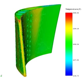
Example of Thermal Results in TAS view
Pre/Post Processing
The ability to efficiently define and construct a model, as well as review and critique the solution, is an important aspect of any design system. This is especially true for a cooled turbine airfoil design, given the extremely intricate geometry, detailed hot-gas flow physics, complex internal cooling airflow properties and final metal and coating temperature distributions. While CTAADS greatly reduces the time to generate a good cooling design, significant attention has been given to improving CTAADS pre and post processing capabilities, with several 3D visualization tools being added to facilitate model construction and validation.
The imported CFD flow field can now be displayed as a 3D view after being scaled to user-defined conditions. Constant radius airfoil cross sections can also be overlaid in the 3D view. This tool provides a quick means for reviewing the imported CFD flow field and comparing it to the 3D solid model before transferring it to STAN7.
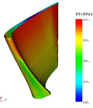
CFD Flow Field 3D Visualization
Another new 3D tool displays a schematic of the 1D internal flow network, including nodes, node identification numbers, node type (Internal or Boundary), branches, branch identification numbers, and resistance model type. After solving the internal flow network, results can be displayed in the 3D view, including pressure and temperature for nodes, and mass flow rate, velocity, and cool-ant heat transfer coefficients for branches. Both constant radius airfoil cross sections from the 3D solid model and CFD file computational sections can be overlaid on the internal flow network schematic. The new features provide an efficient means for cross-referencing GFSSP nodes and branches to specific cooling locations, assess model fidelity to the defined cooling scheme, visualize how the model fits within the 3D airfoil shape, confirm the solid model and CFD flow field are in the same geometric space and inspect predicted internal cooling airflow properties. Deficiencies in the cooling configuration or the modeling technique can quickly be identified and corrected.
Another new feature is the option to display thermal results directly in CTAADS without having to launch an external TAS application. The new TAS view allows quick access to the TAS thermal model, plus many unique options for reviewing the results, and an option to export TAS thermal results to ANSYS or TECPLOT.
The CTAADS upgrades mentioned in this article represent improvements that have been completed over the past two years, but are not a complete list. CTAADS has undergone many other enhancements and even more are planned for the near future. Be sure to contact Concepts NREC for the complete details.


