Why Meanline Scripting is Becoming Essential for Turbomachinery Design
Manual meanline design can sometimes feel less like design and more like managing a chain of tiny decisions.


This Blog post gives a brief outline of the throughflow method for turbomachinery flows and presents the calculated performance results of a Single-Stage Axial-Flow Compressor validation.
The throughflow method for turbomachinery performance prediction is a quasi-three dimensional CFD method that solves azimuth-averaged flow in the meridional plane. Using an azimuth-averaged approach reduces the grid resolution requirement in the tangential direction to only two points (one cell), with a corresponding reduction in the computational cost relative to a full 3-D CFD simulation. For example, for a 3-D case with 100 grid points in the tangential direction, the throughflow case will run approximately two orders-of-magnitude times faster than a corresponding 3-D CFD simulation.
Throughflow methods provide a reasonable trade-off between speed and accuracy and are useful for performing parametric-studies early in the conceptual and preliminary design phases [1]. An integrated throughflow solver is incorporated in the Concepts NREC’s Agile Engineering Design System®.
Easy Access to Throughflow Solver Loss Models
In lieu of resolving the tangential flow direction, throughflow solvers use body-force source terms to capture blade profile losses and turning effects and shock losses. The loss models are derived primarily from the Koch-Smith model for compressors and the Ainley-Mathieson model for turbines.
The Concepts NREC’s Agile Engineering Design System® provides access to an integrated throughflow solver (grid generation, pre-processing, post-processing, etc.) and it provides options for different loss and deviation models, Figure 1. The built-in throughflow solver also provides a set of default settings. These losses and settings can be calibrated to match actual performance data.
The accuracy and utility of the methodology was indicated by performing a set of throughflow validation cases [1].
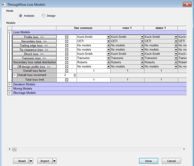
Figure 1: Some of the options for Through-Flow Loss Models
Overview of GT2015-43763 Validation Cases
Reference [1] presents a set of validation cases. These cases include: NACA cascade loss-bucket calculations (loss-coefficient versus incidence angle); DCA cascade loss-bucket calculations; performance map calculations for the DFLVR Single-Stage Axial-Flow Compressor and a study of the Cambridge Low-Speed Turbine.
The DFLVR Single-Stage Axial-Flow Compressor is a high-speed compressor tested in Germany in the 1970s. The compressor produces a pressure ratio of 1.51 while operating at a relative tip Mach number of 1.4 at the design point. Results for this case were presented in 2015 [1] and are repeated here.
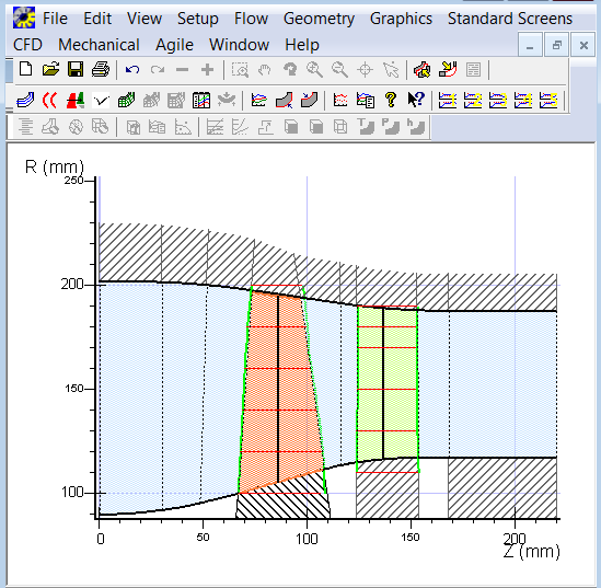
Figure 2: Meridional View of DFLVR Single-Stage Axial Compressor Throughflow Model
The compressor meridional view is shown in Figure 2 and was generated by the throughflow solver pre-processor. A set of throughflow Single-Stage Axial-Flow Compressor validation runs was built by accepting the default parameters for the loss models and running 55%, 85%, and 100% speed-lines. At least nine throughflow cases were run for each speed. The efficiency and pressure-ratio results are compared to experimental data and 3-D CFD results in Figure 3.
Reference [1] concluded that the throughflow solver did quite well in capturing the magnitude and characteristic losses in the stage for the DFLVR Single-Stage Axial Compressor. They also noted that the low-speed line is somewhat higher in performance relative to the test performance values.

Figure 3: Predicted Performance using Default Models/Settings, Reference [1]
Remarks
The throughflow solver is fast and allows easy access to loss model settings and parameters via a graphical user interface window. Algorithm updates/settings that build on the improvements presented in [1] are being considered.
References
[1] Andersen, M. and Bonhaus, D.L., "A Comprehensive Throughflow Solver Method for Modern Turbomachinery Design," ASME Turbo Expo 2015, GT2015-43763, June 15-19, 2015, Montreal, Canada.
Tags: CAE Software

Manual meanline design can sometimes feel less like design and more like managing a chain of tiny decisions.

For most turbomachinery engineers, optimization isn’t a new idea. It’s a critical part of their workflow that can’t be overlooked. But sometimes that crucial step isn’t easy to get to.
It’s no secret that turbomachinery design has been one of the most demanding CAE environments, thanks to tight tolerances, complex physics, and long design cycles. That hasn’t changed in 2026, but...