It’s a straightforward question, but many turbomachinery engineers can’t easily explain the physics behind blade twist. Some shorter high-pressure turbine (HPT) blades appear nearly 2D in shape (little or no twist). Blade twist is more commonly seen in taller turbine blades, which should give an immediate clue as to origin of blade twist.
 As with many other turbomachinery blading design questions, the origin of twist can be explained by drawing vector diagrams for the appropriate sections, in this case, for a turbine blade hub, mean, and tip blade sections. The following figure shows such a diagram for a free vortex blade design. Three main velocity components are shown: ‘U’, the wheel speed, ‘W’, the flow velocity in the relative frame, and ‘C’, the flow velocity in the absolute frame. The tangential component of the absolute velocity, Cɵ, is also shown for each section. Remembering turbomachinery vector diagram addition, relative velocity + blade speed = absolute velocity, which checks out for the vector diagrams shown in this figure.
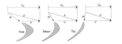
The reason for blade twist becomes apparent after studying this figure. For approximately the same inlet absolute velocity, the relative inlet velocity, and more importantly, for twist, the relative inlet angle varies significantly from hub to shroud because ‘U’, the wheel speed, varies so much. The relative blade angle at the hub is fairly large, and in the opposite direction of the blade exit angle, leading to a lot of turning and low section stagger angle. The relative flow angle at the tip is much lower, even negative, leading to an inlet blade angle that is in the opposite direction as the hub section, and with less blade turning to the exit of the blade (the blade exit angle is relatively constant from hub to shroud in this example), leading to a lot of blade section twist from hub to shroud. So, it is the fact that U varies with radius from the hub to shroud of a turbine blade, and with U, the relation between the absolute and relative velocities and flow angles, that leads to blade twist. Going back to the shorter HPT blades, the difference between hub and shroud radius and, consequently, wheel speed is much smaller, allowing these types of blades to be made of constant section with little or no twist, with little or no aerodynamic impact.
Blading can be designed with different radial equilibrium solutions, leading to different radial profiles of work extraction, and different radial profiles of Cɵ. In the case of the free vortex design, shown in the figure above, RCɵ is constant, leading to the distribution shown, with lower Cɵ at the larger radius. Other radial equilibrium solutions are possible, such as linear forced vortex, or parabolic forced vortex. These distributions change the radial work distribution, as well as the twist distribution, but, typically, still lead to blading which is considered twisted. The radial work distribution can impact blade twist, but the change in radius from hub to tip is the main driver.