Why Meanline Scripting is Becoming Essential for Turbomachinery Design
Manual meanline design can sometimes feel less like design and more like managing a chain of tiny decisions.


Low reaction stages are often used as control stages of steam turbines, ORC turbines, drive and rocket turbopump turbines. Some of the benefits of low reaction stages vs higher reaction stages are:
Smaller radial size (and weight) for the given power and rotation speed
Compatibility with use of partial admission, which is used to accommodate low volumetric flow, with the needed low pressure gradients in the rotor blades to reduce leakage penalties
Both above factors allow increasing of nozzle and rotor blade heights
Smaller radial size provides lower disk rim speeds and disk stresses
Low reaction generally means lower axial thrust of the rotor
Velocity stage configurations are possible for low reaction designs (Curtis stage for example, Fig.1). Velocity stages allow further reduction in radial size and increasing blade heights
Zero swirl at exit of such stages is often desired design property, but some turbine applications and sub-stages of Velocity stages may require substantial negative swirl in order to amplify reduction in radial size and increase in blade heights.
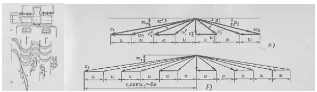
Figure 1. A Curtis velocity stage. Typical velocity triangles of Curtis stage with two and three rotors
To start a preliminary design of a turbine some common rules are often use based on use of flow and loading coefficients (Cm/U, deltaHtt/U^2 in Smith charts), or flow coefficient and stage adiabatic velocity ratio (U/Cs), however these charts/relationships typically are not accommodated for low reaction stages with arbitrary swirl.
A simple set of rules is presented below, which may help in setting sensible preliminary design of zero reaction stages, including velocity stages:
Considered input data
𝜑 - velocity coefficient of the nozzle, = (1 - KE loss coef.)0.5 ~…0.95..0.98…
𝛼1- flow angle at nozzle exit (measured from mrd)
𝛼exit - flow angle at stage exit (0 deg – zero swirl)
m - number of rotors in the Curtis stage
𝜂ts - efficiency, t-s
The outputs are
U/Cs - estimated optimum adiabatic velocity ratio of the stage, Cs = (2*deltaHts)^0.5
or
𝜓 – estimated loading coefficient, ΔHtt/U2
𝜑m – estimated flow coefficient, Cm/U
estimated flow angles in velocity triangles


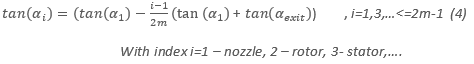
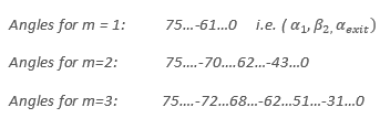
For a typical value of flow angle at the 1st nozzle exit selected at 75 degrees from meridional direction, using (3) and (4), the absolute and relative exit flow angles can be estimated:
The above relationships assume that radial size (i.e. rotation velocity) and meridional velocity are the same for all blade rows.
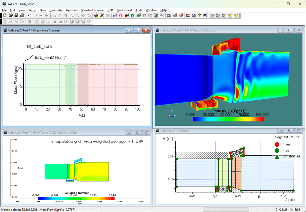
An example of single rotor stage design with convergent-divergent supersonic nozzle, executed via optimization can be found here:
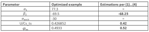
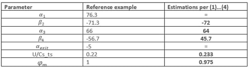
Using data from that case (it reports reaction about 3%, supersonic rotor, labyrinth seal and meridional nozzle-rotor gap leakages, ~ 45% admission), vs above estimations (assumption of zero reaction):
Table 1. Comparing preliminary estimations with the optimized single stage geometry
A Curtis stage example, set in Axial (using non-optimized geometry per Sheglyaev text book, for 24% admission):
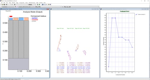
Table 2. Comparing preliminary estimations with the reference Curtis stage geometry
Difference in the flow angles (rotor 2) is mostly due to reduced meridional velocity in rotor 2 vs rotor 1, as it can be observed in Fig. 2. (i.e. assumption of the constant meridional velocity in (1)..(4) is violated).
The suggested relationships give a reasonable estimations of U/Cs (or loading coefficient, if estimated t-s efficiency is known) and flow angles, sufficient to set size and construct initial geometry of low reaction stages, including velocity stage configurations, with arbitrary target swirl at exit.
If you have any questions or comments, please let us know in the comments section below or contact us at info@conceptsnrec.com.
Tags: CAE Software, Turbines, Engineering

Manual meanline design can sometimes feel less like design and more like managing a chain of tiny decisions.

For most turbomachinery engineers, optimization isn’t a new idea. It’s a critical part of their workflow that can’t be overlooked. But sometimes that crucial step isn’t easy to get to.
It’s no secret that turbomachinery design has been one of the most demanding CAE environments, thanks to tight tolerances, complex physics, and long design cycles. That hasn’t changed in 2026, but...