Why Meanline Scripting is Becoming Essential for Turbomachinery Design
Manual meanline design can sometimes feel less like design and more like managing a chain of tiny decisions.


Expanding design capabilities for advanced high-performance turbines for steam and organic Rankine cycle power generation is a constant area of focus in developing Concepts NREC’s Agile Engineering Design System ® (AEDS) software.
Cycle and operation requirements, as well as a wide range of operating conditions and volumetric flows, are often required for the design of turbines with diverse geometries. Some typical design tasks and available new/existing features within AEDS are described here.
Overall Performance Prediction in AXIAL™ for Steam Turbines
Over years of development and validation, AXIAL has proven to be a reasonable tool to design and predict performance of various classes of turbines. Two more cases were added as examples (Figure 1) for large power generation turbines for supercritical and saturated conditions, including the effects of steam reheat and wetness separation.
As a rule, these geometries include a control stage with variable admission, high pressure (HP), intermediate pressure (IP) and low pressure (LP) cylinders, each with multiple stages.

Figure 1 - Supercritical Power Generation Turbine 800 MW K800-240 and Saturation Steam Power Generation Turbine 100 MW K1000-60/3000.
Design of Control Stages
Curtis and Rateau geometries can be designed in AXIAL, with partial admission considered. Careful validation work was undertaken for subsonic and supersonic nozzles in design and off-design operating conditions, shown in Figure 2.

Figure 2 - Performance prediction of Curtis stages; AXIAL vs. test data for drilled [left] and bladed nozzles [right].
(Courtesy PerAero Turbine Designs, LLC)
To start an automated Curtis stage design in AXIAL, the Macro script option may be used. Further geometry refinement is done in the redesign or analysis mode, manually or using automated optimization via TurboOPT II™ and integrated or 3rd party optimizers, such as IOSO™, modeFRONTIER®, and Isight™, among others.
For 3D geometry development in AxCent®, all through-flow, blade-to-blade and 3D CFD solvers have a special option for aero calculations in the active jet domain to support the design of blade section profiles and blades. Parametric or arbitrary blade section types with arbitrary stacking are available for manual or automated optimization.
Performance and geometry of supersonic convergent-divergent bladed geometry (Figure 3) can be estimated in AXIAL and finalized in AxCent.
Strict real fluid thermodynamics and loss model validations extended into incompressible fluids ensures reasonable predictions in liquid and the ultrasupercritical domains of real gases.
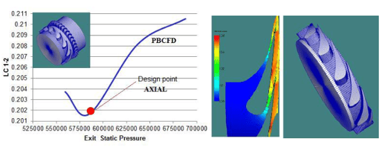
Figure 3 - Loss prediction and profile development of a supersonic nozzle at Ma ~1.7.
HPT Stage Design
From preliminary design to 3D geometry, AEDS handles low/negative-to-high reaction flow, consistent with modern technologies such as Compound Lean, 3DS, and Dense-Pack, among others. The development of high-performance multistage turbines requires significant optimization effort, aided by suitable geometry parameterization, the ability to account for interactions between blades, and stage interactions due to secondary flows and clearance effects, all of which are available to the AEDS users.

Figure 4 - Initial and optimized (right) geometry of HP cylinder, overall efficiency target >90%.
Figure 4 shows an example of preliminary flow path optimization for a steam turbine high-pressure cylinder (considered as a single domain for control stage and two groups of HPT stages). Radial locations, flow path contours, pressure ratios, reactions, and main parameters for the blade sections of the control stage, and the first and last stages in each of HPT groups were set to variable. Flow and geometry parameters for nozzles and stators were set by interpolation for the intermediate stages. Constraints were set for the estimated structural data, geometrical tolerances, blade loading and reactions, and pressure field. Optimized geometry produced credible results in the Smith chart metrics.
The development of preliminary 3D geometry often relies on using blade-to-blade CFD, which tolerates shock effects and flow separations. Automated blade section optimization can be set for individual or multiple blade sections at the specified span.

Figure 5 - Bezier blade section optimization using Blade-to-Blade CFD.
Figure 5 shows an example of a section optimization for an arbitrary Bezier profile, delivering better aero loading and >30% reduction in losses.
Normalized curvature distribution has been added recently to AxCent, providing excellent control for subsonic and supersonic profiles. These do not depend on chord and camber, and offer the ability to reuse the curvature distributions in different projects.
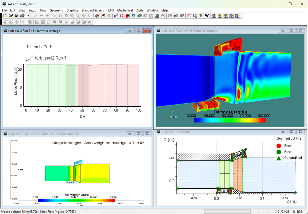
Arbitrary flow path contours, sections, and stacking are all instrumental for coupled 3D CFD optimization, to mitigate penalties from secondary and clearance flows and non-uniform flow profiles, for an intermediate optimization step (Figure 6).

Figure 6 - Full 3D CFD optimization using S-contouring, sections, and stacking of nozzle shroud to meet the distorted flow profile at the inlet.
IP and LPT Stage Design
The AXIAL features described beforehand deliver a preliminary feasible flow path for groups of IP and LP stages. Preliminary structural constraints, limitations in swirl and Mach numbers (for diffuser coupling), and estimates for off-design operation - including at zero power level of the last stage - can now be considered.
Complex 3D shaping of tall twisted blades delivers improved performance due to better span wise flow distribution, profile, secondary flow effects, and weakening TE vortex sheet mixing loss. This is achieved by minimizing divergence of streamlines on the pressure and suction sides of the nozzle based on full 3D CFD flow analysis of the stage, Figure 7.

Figure 7 - Suction and pressure side streamlines in the nozzle domain before/after 3D CFD optimization of an LP stage geometry.
Tags: CAE Software, Renewable Energy, Turbines

Manual meanline design can sometimes feel less like design and more like managing a chain of tiny decisions.

For most turbomachinery engineers, optimization isn’t a new idea. It’s a critical part of their workflow that can’t be overlooked. But sometimes that crucial step isn’t easy to get to.
It’s no secret that turbomachinery design has been one of the most demanding CAE environments, thanks to tight tolerances, complex physics, and long design cycles. That hasn’t changed in 2026, but...