Why Meanline Scripting is Becoming Essential for Turbomachinery Design
Manual meanline design can sometimes feel less like design and more like managing a chain of tiny decisions.


If you are a turbomachinery engineer, you know you can spend days, weeks, or even months analyzing various design iterations, looking for the optimal choice for the application. When you go to present your final design for review, you want it to look as good as you know it is. Choosing the best post-processor for CFD results can not only save time in creating the desired views, but also show solutions at their best. Without proper post-processing, your solution can lose that "je ne sais quoi" that made it the best design for the application. In other words - it has to look as good as you know it is.
Turbomachinery designers have had to make a choice: use either a general-purpose CFD solver or one specialized for turbomachinery. Many choose the general-purpose CFD solver, prioritizing CFD functionality over turbomachinery-specific features. But this meant that designers had to give up on some important features and functionality.
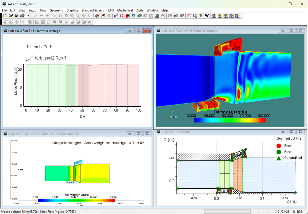
Rotating equipment designers care about very specific things, which may or may not be easily available or configured in more general post-processors. These include things like line plots, which are key to understanding detailed performance aspects, and 2-dimensional sections, which are tied in real-time to the 3-dimensional results. Designers like it when the analysis axes are visualized against the geometry in the traditional turbomachinery manner, with streamwise, blade-to-blade, and blade hub-to-tip standing in for the more common orthogonal (x,y,z) or polar (r,θ,z). Savvy rotating equipment analysts know these very useful other-directional axes as S1, S2, S3 – and more pertinent information can be gleaned from study along these orientations than from the other conventional axis systems.
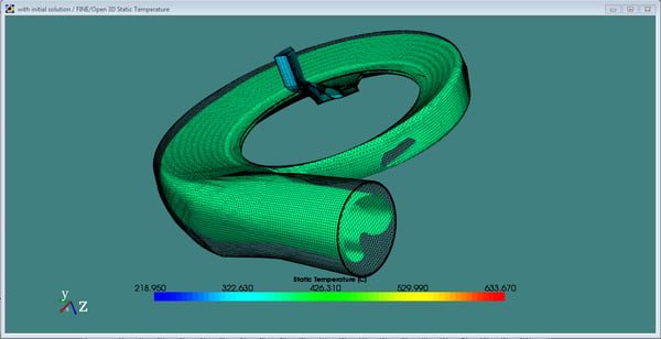
Of course, 3-dimensional flow fields with vector or contour views can tell an experienced engineer much of the qualitative nature of the solution, but also having simpler information available can help anyone. Basic data, such as predicted overall efficiency or overall performance at multiple operating points, can provide a firmly quantitative assessment of the benefit of one geometry versus another.
Can you get the best of both worlds? The answer is yes. You can have a world-class gridding and solving tool, such as NUMECA International's FINE™/Turbo, coupled with a turbomachinery-specific post-processor, pbPost™. Sometimes presentation is everything - so why not put your designs in their best light?
Tags: CAE Software, CFD

Manual meanline design can sometimes feel less like design and more like managing a chain of tiny decisions.

For most turbomachinery engineers, optimization isn’t a new idea. It’s a critical part of their workflow that can’t be overlooked. But sometimes that crucial step isn’t easy to get to.
It’s no secret that turbomachinery design has been one of the most demanding CAE environments, thanks to tight tolerances, complex physics, and long design cycles. That hasn’t changed in 2026, but...