In my previous blog post, “How the Design of a Wind Turbine Differs from other Types of Turbines”, I showed that the very small pressure drop across the rotor makes wind turbine design different from other types of turbines. This blog will focus on the best method to design a wind turbine rotor based on the fact that only kinetic energy is available to extract from the wind.
A common wind turbine design procedure uses the Blade Element Momentum (BEM) theory. BEM determines the change in momentum through the rotor disk by summing the forces on the differential blade elements in an annulus' δr, swept by each element as shown in Figure 1. The airfoil section of each element along the span of the rotor generates lift and drag which resolve to a tangential force to rotate the blades and provide power as well as an axial thrust that the structure must withstand. The integral of all the differential sections provides the power and thrust for the rotor. This method assumes that each section is independent and does not influence the other sections with radial interaction between the annulus streams.
This assumption is valid for an axial induction factor near the optimum Betz limit value of 1/3. Therefore, it is a reasonable method for predicting performance at the design point.
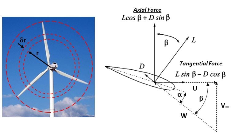
Figure 1. Blade Element Velocities and Forces
For optimum power, the airfoil sections need high lift and low drag. Figure 2 shows the lift to drag coefficient versus angle of attack for a NACA 5518 airfoil. The lift to drag ratio for an airfoil in a wind turbine is dependent on the angle of attack and the Reynolds number. Each section should use an airfoil section design that is optimum for the Reynolds number at that blade section and set at an angle of attack for maximum lift to drag ratio.
The design of the rotor is the process of optimizing each section for the conditions at that section, as with other types of turbine design. Usually standard airfoil shapes that are well characterized and tested are used for each section because there is a large body of airfoil data and research that can be used to quickly arrive at a near optimum rotor design.
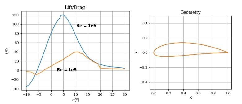
Figure 2. Lift/drag Ratio Versus Angle of Attack for a NACA 5518 Airfoil at Two Reynolds Numbers
The design process starts with a given blade count and rotational speed, then the airfoil is selected for each section, the stagger angle is set for an angle of attack at maximum lift to drag ratio, and the airfoil is scaled for the optimum chord length, which, is the chord length that achieves an axial induction factor of 1/3 for that section.
Using the techniques discussed here, that are embedded within a wind turbine design code, I designed a wind turbine and predicted the performance to compare to a commercial turbine of the same size. The results are shown in Table 1 below. My turbine design was very close to the same power as the published results for the commercial turbine. The commercial turbine has an estimated blade Reynolds number that is about 5 times that of my own turbine design. That estimate is based on the increased chord length of the commercial turbine over my turbine. The optimal chord length is dependent on the airfoil sections that are used and structural concerns.
Table 1. Wind Turbine Design Comparison
|
Parameter
|
Units
|
Mine
|
LN3500
|
|
Wind speed
|
m/s
|
12
|
12
|
|
Rotor Diameter
|
m
|
3
|
3
|
|
Number of Blades
|
-
|
5
|
5
|
|
Rotational speed
|
RPM
|
700
|
700
|
|
Airfoil
|
-
|
NACA 5518
|
?
|
|
Reynolds Number
|
-
|
1e5
|
~5e5
|
|
Angle of Attack
|
Deg
|
10
|
?
|
|
Aero Power
|
kW
|
3.11
|
3.13*
|
*Assumes 96% generator efficiency
This brief exercise highlighted just the very basics of wind turbine design. In a future blog, I will discuss in more detail how to find the optimal chord length, how to set the rotational speed, and how to determine the number of blades.