When designing a new compressor or pump, most of the focus is put on the impeller and diffuser because they are the elements that are responsible for the work input and its conversion from kinetic energy into static pressure. However, they are not the only elements in a typical turbomachine stage. The volute can also play a significant, and sometimes dominant, role in stage performance. This blog will explore important factors in volute design.
At the discharge of a radial turbomachine, the flow can be led to a tangential exit pipe, using a volute. The design of a successful volute involves several factors: inlet flow conditioning, proper volute sizing, throat placement and tongue configuration, and the exit conical diffuser layout.
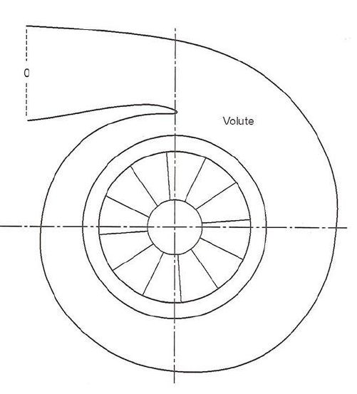
A simple example of a volute with rotor separated by a short vaneless space
Designing for a volute does not begin with the volute, but rather with upstream elements. A particular area of focus is how the flow comes onboard the volute. The flow must be prepared for the type of volute being used and conditioned appropriately. If the flow entering the volute is not prepared then volute effectiveness is already handicapped and performance will be sub-optimal. How you condition the flow to ensure volute success is dependent on the machine for which the volute is being designed. In close-coupled impeller/volute designs the impeller is often designed with more back sweep to help reduce volute inlet velocities and thereby, reduce losses, improving overall stage performance. If a vaneless diffuser is used before a volute, the diffuser usually includes some pinch to help condition the flow.
The sizing of the volute scroll can also have a dramatic effect on the overall performance map of the pump or compressor. Volute scroll cross-sectional areas are defined on sections around the circumference of the volute, from 0 to 360 degrees, with the tongue or cutwater at 0 degrees. At the compressor or pump design point, a volute is often designed to have little to no static pressure recovery in the scroll portion, through careful control of the circumferential section areas. The sections are sized, using constant angular momentum, but can also be slightly increased in size around the circumference to account for boundary layer growth. If a volute is mismatched to a pump or compressor, the performance curve (pressure rise or efficiency as a function of flow) will be shifted to higher or lower flows. If the volute is undersized, the curve is shifted to lower flows. If oversized, the performance curve is shifted to higher flows. Sometimes this shift is done intentionally to fine-tune a machine to a desired flow range.
Scroll sections can have varying shapes with different impacts on performance, largely due to friction. Even though a circular volute cross section provides the smallest wall area per unit volume, in the end, the shape is most often dictated by installation geometric constraints. Compressor designers typically use overhung volutes, while commercial pump designers tend to favor a symmetric volute.
Another critical aspect of volute design is the proper generation of the tongue or cutwater because the tongue shape can have a big impact on performance and range. There are many factors that need to be considered, depending on the application. These factors can include manufacturing method and tolerances, material stresses, fluid erosion, tongue angle, offset from the upstream impeller, diffuser vane clocking, etc.
There are also performance and range issues to consider. A well-designed tongue with small relative thickness may provide the lowest losses but may reduce operation range. A large radius tongue will provide a wider operating range, but may also incur increased design point losses.
Also critical to tongue design is the throat (or minimum) area the tongue generates. This area is what sets the capacity of the volute and is where the exit diffuser begins. This can be a very difficult area to model in CAD with complex geometric shapes. Care must be taken that the resultant throat area is as intended or the volute will not perform as expected. It is also important that the tongue and throat geometry flow is such that the downstream volute exit diffuser will perform well.
The final part of the volute that needs to be sized appropriately is the diffuser, from the volute throat to the mating pipe flange. There can be a sizable area ratio for this section, and a lot of performance can be lost in stalling this conical diffuser by not providing enough length for good diffusion. Conical diffuser performance maps indicating expected pressure recovery for a given area ratio and length can be utilized for quick layout of this element.
At first, a volute appears to be rather simple and straightforward to layout, but designs should be checked by modeling if the volute design is outside tested experience from previous designs. Empirical modeling can be a quick and effective way to accomplish this. Computational Fluid Dynamics (CFD) can also be an effective tool in evaluating volute geometry and increasing confidence in the expected design performance.