In my blog Flow Coefficient and Work Coefficient, I outlined the basic concept behind the flow and work coefficient. These nondimensional parameters are widely used to characterize axial and radial turbomachinery. Another widely used parameter for radial design is “specific speed”. For something with such a finite name, specific speed is perhaps the most mysterious and non-intuitive parameter in all of turbomachinery. In this blog, I'll lay the ground work for understanding specific speed.
Recall the flow coefficient for axial machines is:

(See the Cheat Sheet below for equation details.)
There are several variations on how flow coefficient is defined for radial machines. This is due to the fact that radial machines often have significant variation in density, area, and, by definition, radius. A common method of defining flow coefficient for radial turbomachinery is expressed as:

The subscript 1 is for the inlet and the 2 is for outlet in the case of a compressor. The convention is reversed for a radial turbine where 1 is the exit and 2 the rotor inlet. It’s important to realize that the definition is just a convention and doesn’t reflect any single specific physical state or location.
With a little math, we can reduce the above equation to:
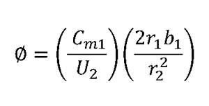
We can see this looks a bit like the corresponding definition for flow coefficient in axial machines but with an extra geometry term added in.
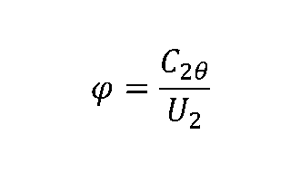
For work coefficient, the difference between the axial and radial definitions is minimal. More often than not, the swirl at the radial compressor inlet (or exit for a radial turbine) is zero. If this is the case, then the work coefficient can be expressed as:
Over the years, the performance of pumps and compressors was found to correlate with a combination flow coefficient and work coefficient. Lines of this similar performance were called specific speed and found to roughly follow the equation:

The term is nominally dimensionless but various forms of it have been put forward which incorporate dimensional terms as well.
The variation in specific speed can best be observed visually. The two figures below show the general shape change, as a function of increasing specific speed for hydraulic turbines (top) and pumps (bottom).
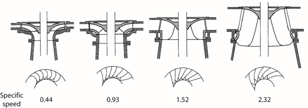
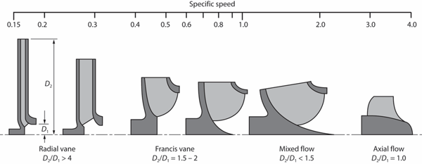
Figure from textbook Centrifugal Pump Design and Performance
by David Japikse, William D. Marscher, and Raymond B. Furst
Note that since there is no resulting length scale in the specific speed term, the overall shape, not the physical size is what is indicated by the specific speed.
In my next blog, I will look deeper into the effect of specific speed on machine performance.
Cheat Sheet:
A : area
b : breath or height of the passage
C: absolute velocity
m : mass flow
r : radius
U : wheel speed (rad/sec*r)
ρ : density
Φ : flow coefficient
Ψ : work coefficient
Subscripts:
1: inlet region for compressors, outlet region for turbines
m : meridional direction
θ : tangential direction