Imagine you're finishing an impeller blade with a ball end mill. The drawing calls for a specific surface finish, but now you need to determine the toolpath parameters that will achieve it. Should you reduce the stepover? What is the target cusp height? And how closely does that theoretical cusp height relate to the surface roughness that will actually be measured on the finished part?
These questions are common in precision machining, yet the relationship between toolpath geometry and surface finish is often presented as a simple formula without explaining the underlying geometry or its practical limitations.
In reality, cusp height is only one piece of the puzzle. The theoretical cusp height is determined by two things: the diameter of your tool and your stepover distance, but the measured surface can also be influenced by the surface shape, machining dynamics, and other process parameters. Understanding how cusp height is determined and how it relates to both theoretical and measured surface roughness helps engineers make more informed decisions about machining strategy, cycle time, and part quality.
What is Surface Roughness?
No machined surface is perfectly smooth. When viewed at a microscopic scale, even a surface that appears polished contains small peaks, valleys, grooves, and other irregularities. Surface roughness describes these closely spaced variations in the surface profile and provides a way to quantify the texture that is inevitable in the manufacturing process.
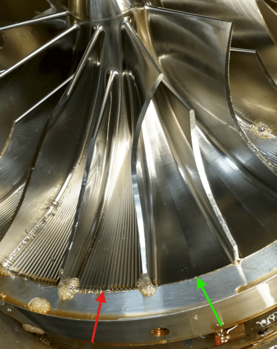
The red arrow (left) shows a larger stepover, or more distance between each tool pass, which leaves larger cusps and a rougher surface. The green arrow (right) shows a smaller stepover, with tool passes closer together, creating smaller cusps and a smoother surface finish.
Surface roughness is commonly expressed using measurements such as Ra and Rz. The average roughness, or the deviation of the surface profile from its mean line, is represented by Ra, while Rz focuses more on the vertical distance between high peaks and low valleys. Although both are describing the same general surface, they measure it differently.
Why Surface Roughness Matters
The surface finish specified on an engineering drawing is not simply a cosmetic requirement. Surface texture can influence how a component performs, particularly where surfaces interact with fluid or touch other components.
Depending on the application, surface roughness can affect:
In turbomachinery, for example, the roughness and direction of machining marks on an aerodynamic surface may influence the flow across that surface. This is one reason a blade may have a tighter surface finish requirement than the surrounding hub. The functional requirements are different, so the drawing may allow different levels of roughness across the same component.
Measuring the finished surface verifies whether the machining process produced a part that meets those requirements.
What Determines Surface Roughness?
Surface roughness is created by a combination of toolpath geometry and real-world machining conditions.
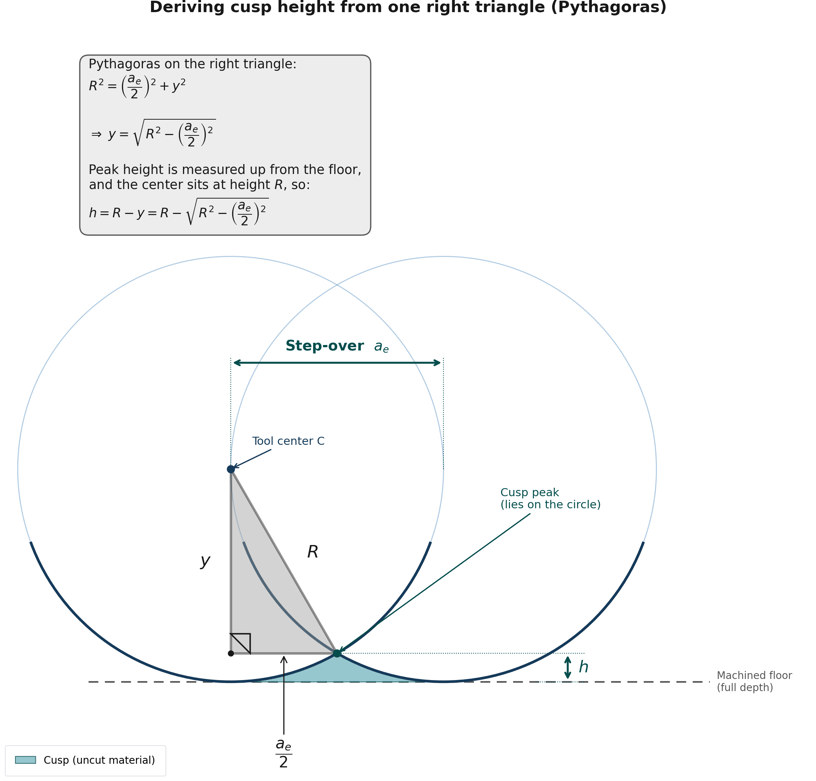
When a ball end mill works its way across a surface, it leaves small ridges of material between passes. These ridges, commonly called cusps, create a predictable geometric pattern. Their height is determined primarily by the tool diameter, the distance between tool passes, and the relationship between the cutter and the part surface.
Before we look at Ra and Rz, we need the foundational formula that links tool radius (R), stepover (ae), and cusp height (h):

This can also be written in terms of tool diameter:

Because the cusp height is usually incredibly small relative to the tool diameter, machinists use a highly accurate simplified formula for quick calculations:

Where:
h = Cusp height
ae = Stepover distance
D = Cutter diameter of the ball end mill
(Note: Keep your units consistent! If D and ae are in inches, h will be in inches. If they are in mm, h will be in mm.)
From Cusp Height to Rz and Ra
Cusp height describes the geometry left behind by a ball end mill, but engineering drawings typically specify a surface roughness value such as Ra or Rz. So how do you select toolpath parameters that produce the desired finish? Understanding how these measurements relate is essential.
What Rz Measures
Rz measures the vertical distance between the highest peaks and lowest valleys within a sampling length. Unlike Ra, which averages the entire profile, Rz looks at isolated peaks and valleys.
As a result, two surfaces with similar Ra values may have noticeably different Rz values if one contains deeper grooves or higher peaks than the other.
In a theoretical, perfect CNC machining environment using a ball end mill, the maximum peak-to-valley height is the cusp height. Therefore, Rz is directly equal to h.
What Ra Measures
Ra (Arithmetic Average Roughness) is the average height deviation of the surface profile from its mean line over a specified sampling length. Instead of focusing on the tallest peaks or deepest valleys, Ra averages all of the profile's deviations into a single value.
A ball end mill creates a repeating, wave-like geometric pattern, so the relationship between the peak (Rz) and the average (Ra) can be mathematically approximated.
For a theoretical scallop waveform, Ra is roughly 25.6% of the total scallop height:

Because it represents the overall texture of the surface, Ra is the most common surface roughness parameter specified on engineering drawings.
Estimating Surface Roughness from Cusp Height
Machinists have generally used a simple rule of thumb to estimate surface roughness, which follows our formulas above:

This approximation comes from the idealized geometric profile created by a ball end mill. If the only feature on the surface is the repeating pattern left between adjacent toolpaths, then theoretically the average deviation of that profile is approximately one quarter of the cusp height.
The key word, however, is theoretical.
This relationship assumes the finished surface consists only of perfectly formed cusps created by ideal tool geometry and nothing else. In reality, the machined surface is also influenced by factors such as tool wear, cutter runout, machine vibration, chatter, tool deflection, material properties, and cutting conditions. These effects can alter the surface profile, causing the measured roughness to differ from the theoretical prediction even when the calculated cusp height remains the same.
In addition, the curvature of the surface also affects the geometry. The equations above assume the cutter is machining a locally flat surface with a constant stepover. On curved surfaces, the relationship between the tool and the material changes, so the actual cusp height may differ from the theoretical value.
As a result, cusp height should be viewed as a predictor of the geometric surface finish, not a guarantee of the finished part's measured Ra or Rz. It provides an excellent starting point for selecting toolpath parameters and estimating whether a machining strategy is likely to meet the drawing requirements. In practice, manufacturers often target a theoretical surface finish that is two to three times smaller than the drawing requirement. This provides margin for the inevitable effects of machine dynamics, tool wear, runout, and other process variables that influence the final measured roughness.
Calculating Stepover from a Target Finish
Usually, you know what surface finish you need, and you want to calculate what stepover to program. By rearranging the previous formulas, you can solve for stepover (ae).
To achieve a specific Rz (or cusp height h):

To achieve a specific Ra:

Choosing the Right Finishing Tool
The relationship between tool diameter, stepover, and cusp height explains why modern finishing strategies often utilize barrel tools or bull end mills. These tools provide a larger effective cutting radius, allowing for a larger stepover while maintaining the same theoretical cusp height and surface finish.
Increasing the stepover reduces the number of tool passes required to machine a surface, which can significantly reduce cycle time, and ultimately means lower machining costs.
Why is Surface Roughness Important?
Not every surface on a component requires the same level of finish. Engineering drawings often specify different surface roughness requirements for different features because each surface serves a different function within the finished part. Depending on the application, engineers may specify different roughness values to satisfy performance, sealing, wear, fatigue, or other design requirements.
It is also common for different regions of a component to have different surface finish requirements. For example, the blade and hub of an impeller may not receive the same roughness specification. The blade surfaces directly influence fluid flow and may therefore require a finer finish than the surrounding hub, where the functional requirements may differ.
Achieving a finer surface finish generally requires additional machining time. Smaller stepovers, additional finishing passes, different tooling, or secondary finishing operations can all increase manufacturing cost. This is why surface finish specifications should balance functional performance with manufacturing efficiency. Specifying a tighter finish than the application requires may increase cycle time without providing any improvement in part performance.
Once a roughness value is specified on a drawing, the finished surface typically needs to be verified using the appropriate measurement method. Inspection requirements, measurement location, sampling length, and acceptance criteria should be clearly defined so that the measured values can be consistently compared with the engineering specification.
From Theory to Practice
Surface finish begins with geometry but ends with the machining process.
The geometry of a ball end mill and the selected stepover determine the theoretical cusp height, providing engineers with a predictable way to estimate the surface profile that a toolpath will produce. This relationship makes cusp height a valuable tool for selecting machining parameters and evaluating whether a planned strategy is likely to satisfy a surface finish requirement before the first cut.
However, the finished surface is influenced by much more than geometry. Machine dynamics, tool condition, material behavior, cutting parameters, and machining strategy all contribute to the surface roughness that is ultimately measured. While cusp height predicts what should happen under ideal conditions, the manufacturing process determines what actually happens on the part. It should be noted that the direction of measurement will affect the result. Here, we focused on the cusp-to-cusp roughness because that is often the worst case, but it is also important to measure along the direction of cut to get a full picture of the surface roughness.
Understanding both perspectives allows engineers to make better machining decisions. By combining theoretical surface finish calculations with practical knowledge of machining behavior, engineers can choose appropriate toolpath parameters, balance cycle time with part quality, and produce components that meet both engineering requirements and manufacturing objectives.