Why Meanline Scripting is Becoming Essential for Turbomachinery Design
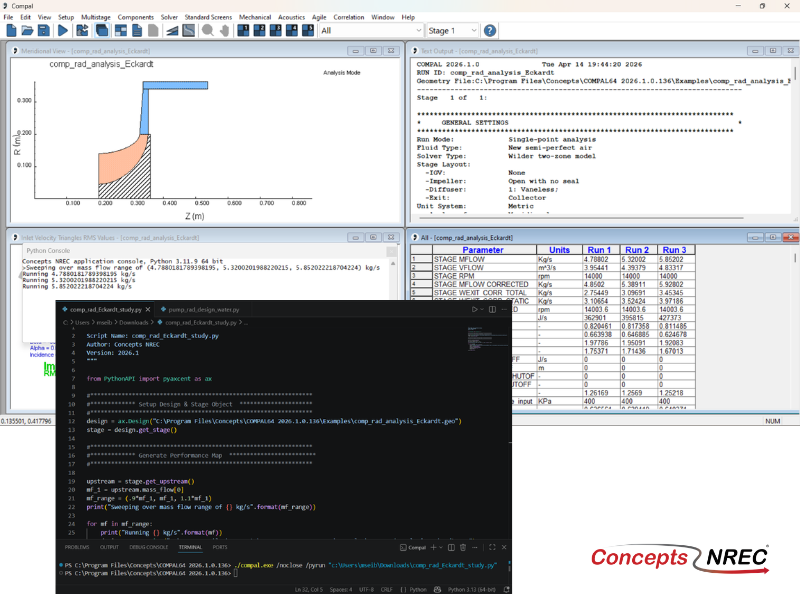
Manual meanline design can sometimes feel less like design and more like managing a chain of tiny decisions.


Even programmers with years of turbomachinery experience run into toolpath problems.
Not because they lack the knowledge, but because the complexity of these components makes certain issues genuinely difficult to anticipate.
That's not a skill problem. It's a visibility problem.
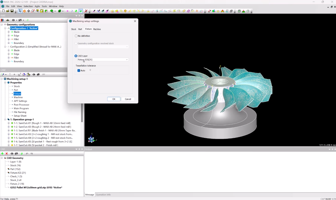
The nature of complex 5-axis turbomachinery programming means that entry strategies, stock conditions, tool orientation, and machine motion all interact in ways that are difficult to fully anticipate without the right software. Workarounds and past experience only go so far.
The good news is that many of these mistakes don't have to make it to the machine anymore. With better simulation, more accurate stock tracking, and purpose-built CAM workflows, programmers can identify and resolve these issues earlier in the process before they become rework, scrap, or lost time.
Below are five of the most common turbomachinery toolpath strategy mistakes, why they happen, and what a more effective workflow looks like.
Tool entry is often treated like a minor setup detail. Default entry strategies are a reasonable starting point, but in complex turbomachinery geometry, the way the tool first engages the material has a direct impact on cutting stability and surface finish.
In critical areas like around leading edges, fillets, and tight transitions, not paying attention to tool entry can result in visible tool marks, increased chatter, premature tool wear, and inconsistent surface finish that can be difficult to trace back to its source.
Defining entry strategies that are matched to the part geometry — rather than accepting defaults — reduces stress on the tool and creates a more consistent starting point for the rest of the toolpath.
For turbomachinery specifically, approaches like edge finishing a hub extension can eliminate a potential entry point in the fillet area, one of the more sensitive regions on these components. Spiral roughing is another strategy worth considering, allowing the tool to engage material gradually rather than plunging directly into it, which reduces load at the entry and improves consistency. Using blending techniques to gradually blend onto the finished surface can also be key for success, especially where multiple toolpaths come together.
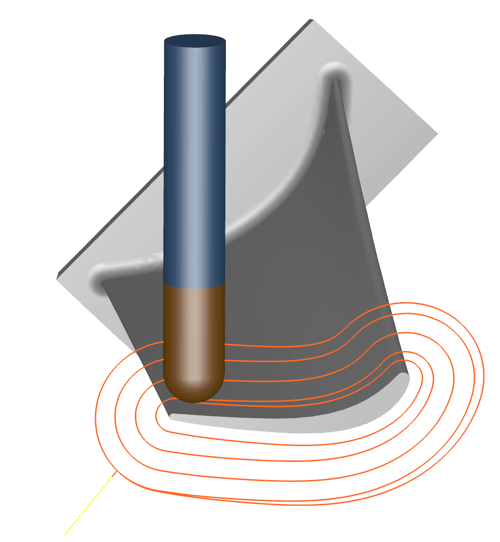
Entry strategies should account for both efficiency and quality. Optimizing purely for speed at the entry point often creates problems that cost more time to fix downstream than the shortcut saved.
In multi-step turbomachinery machining, each operation changes the state of the part. Without clear visibility into what material actually remains, subsequent toolpaths are often programmed based on outdated or incomplete assumptions about stock conditions, and that gap between assumption and reality is where problems develop.
These problems usually look like excessive air cutting, inefficient toolpaths, missed material, or overcutting, all of which create longer cycle times, decreased tool life, and increased risk of rework. But stock management issues can also show up in less obvious ways. In areas where access is already tight, unexpected remaining material can cause the tool to collide with stock that wasn't accounted for, leading to premature tool wear or breakage.
Maintaining an accurate idea of stock conditions throughout the machining sequence is what prevents these issues from compounding. A stock chain manager allows programmers to configure and track how stock evolves across operations, so each toolpath is based on the actual condition of the part rather than an assumption.
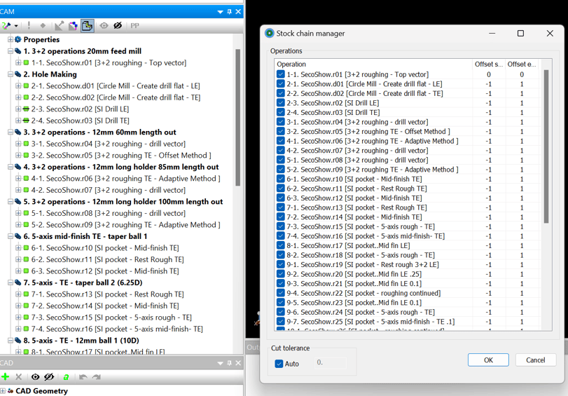
Material Removal Simulation (MRS) adds another layer of visibility, allowing programmers to examine stock and material conditions throughout the toolpath, including checking for collisions between remaining stock and the tool or holder.
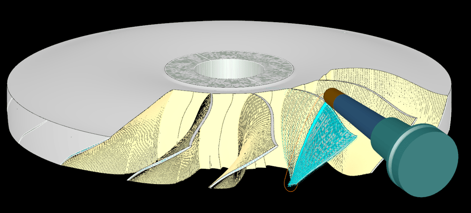
The result is a process where each operation starts from an accurate baseline, which makes outcomes more consistent and reduces the surprises that lead to rework or scrapped parts.
In turbomachinery machining, tool selection involves more than taking into account the diameter and availability. Reach, cutting geometry, and how a tool behaves with different materials all affect how well it performs. Relying on familiar tools without fully considering those factors can create problems that aren't immediately obvious at the programming stage.
Poor tool selection typically shows up as excessive tool wear, uneven surface finish, and difficulty reaching critical areas. In tighter regions, using the wrong tool may result in needing additional passes to compensate for deflection or limited access, which adds cycle time and introduces more opportunity for inconsistency. Some tools simply aren't optimized for blade passages, fillets, or complex components like integrally shrouded impellers, and that mismatch compounds quickly across a multi-step program.
Tool extension - the length of the tool sticking out from the holder relative to the tool shank diameter - is one commonly overlooked factor. Keeping tool extension to less than 3x the tool shank diameter is the general rule for maintaining rigidity, which makes larger diameter tooling preferable where access allows. For longer reach tooling like lollipop end mills, which have a reduced shank diameter and are therefore less rigid, this becomes even more critical.
Starting with the default tool suggested by CAM software specifically designed for turbomachinery components provides a strong baseline. These defaults are informed by the geometry and operation type, which takes some of the guesswork out of the initial selection. From there, programmers can refine based on the specifics of the part. Turbomachinery-specific tool libraries within CAM software make this process more reliable, giving programmers better starting points and clearer guidance for tools that are actually suited to the components they're machining.
Five-axis machining opens up a lot of capability, but it also multiplies the ways things can go wrong.
With multiple axes, small decisions that seem inconsequential during programming can have a significant effect on how the machine actually behaves during cutting.
Collisions and near-misses are the most obvious risk, but the subtler issues also greatly affect part quality. For example, if the tool is pushing into the material rather than pulling, it will tend to vibrate, leaving behind unwanted chatter marks on the surface like waves or ridges. For longer tools this becomes more pronounced, and workpiece engagement becomes an additional consideration. It's best practice to direct cutting forces axially along the shank rather than radially, which reduces deflection and improves stability through the cut.

Tool orientation decisions can also influence where axis reversals occur, which is often easy to overlook during programming. When rotary or linear axes change direction during critical portions of the cut, they can leave visible marks on the blade surface.
Machine envelope constraints add yet another layer of complexity. A toolpath may look feasible in the CAM software, but still impossible for the machine to actually execute. On a shrouded impeller, for example, it may be possible for a tool to reach from the exducer side to meet a previously milled inducer, but the machine may not have the physical ability to swing the head axis to complete the motion.
Getting orientation right means going beyond the system-generated defaults. Simulation tools that show the full machine motion give programmers the ability to see where reversals occur, identify clearance issues, and make targeted adjustments before anything gets cut. Moving those reversals to less critical areas of the blade, and catching clearance problems at the programming stage, is the difference between a toolpath that looks correct and one that actually performs as intended at the machine.
Even with years or decades of experience, when it comes to complex turbomachinery machining, it’s difficult to fully predict machine motion, tool engagement, and clearance just by reviewing the toolpath.
Skipping or underutilizing simulation means programming without visibility into how the full machine will actually behave during cutting. It’s more than just the tool and material that needs to be considered, too. Programmers shouldn’t forget about the holder, fixture, spindle, and tables - items that aren’t shown in the toolpath. That gap tends to show up at the worst possible time, when unexpected collisions, inefficient machine motion, or surface finish problems only become apparent once the program is running on the machine and material is already being removed.
Simulating the complete machining environment allows programmers to see how every component moves in relation to the part throughout the operation, catching clearance issues and inefficient motion before they become costly. Combined with MRS, which tracks stock conditions and checks for collisions between remaining material and the tool or holder, programmers get a much clearer picture of what's actually going to happen before the first cut is made.
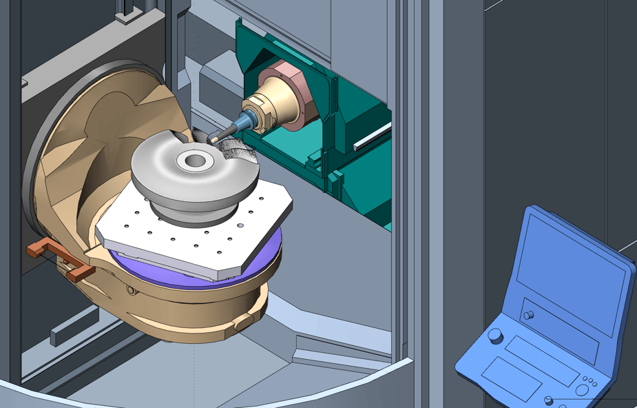
Utilizing simulation is more than just catching mistakes; it's about moving from assumption to verification as a standard part of the workflow. Problems that previously required machine time to discover can now be identified and resolved at the programming stage, which reduces iteration and makes it easier to move confidently from programming to production.
These top toolpath strategy mistakes don’t happen because of lack of skill. They happen because traditional programming has made it difficult to see everything that needs to be considered before the part reaches the machine. Building workflows and using software that reveal those problems earlier is what reduces iteration and makes outcomes more predictable.
With better simulation, more accurate stock tracking, and greater control over toolpath and tooling decisions, programmers can shift from reacting to issues to preventing them.

Tags: Software, CAM Software
Manual meanline design can sometimes feel less like design and more like managing a chain of tiny decisions.
Most programmers have worked with a toolpath that looks reasonable at first but becomes increasingly difficult to manage as programming progresses. Besides being a hassle to deal with, unnecessarily...

For most turbomachinery engineers, optimization isn’t a new idea. It’s a critical part of their workflow that can’t be overlooked. But sometimes that crucial step isn’t easy to get to.