Software Release Notes
The latest functionality in turbomachinery design and manufacturing
Streamlined the ARMD model setup and enhanced rotordynamic fidelity by enabling automatic generation of ARMD Agile link files directly from AxCent. This one-step workflow reduces manual data handling, minimizes transfer errors, and accelerates the overall model-building process.
ARMD 2026.1 includes a new module to quickly estimate the radial stiffness of rolling element bearings.
With a minimum amount of input, ARMD's new rolling element bearing stiffness module permits analysts to quickly estimate the radial support stiffness of common ball and roller bearing designs as follows: Deep-Groove Ball, Angular Contact Ball, Self-aligning Ball, Tapered Roller, and Spherical Roller.
The estimated radial stiffness values neglect the influence of preload, axial force and high-speed rolling element kinematics and are not intended as a replacement for a comprehensive rolling element bearing analysis. ARMD's new rolling element bearing stiffness module can be run as a standalone app but has also been integrated into its lateral rotor dynamics software (ROTLAT). Integration of the rolling element module within ROTLAT permits the analyst to automatically bring the load-dependent radial support stiffness data into the lateral rotor dynamic simulation.
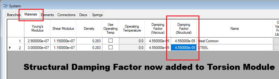
Updated TORSION 2026.1 to now support structural damping. Unlike TORSION's currently available viscous "Damping Factor", structural damping is frequency-independent and proportional to displacement amplitude. TORSION's TORNAT and TORHRM modules implement structural damping as the imaginary component of a complex stiffness. This component is calculated using the inputted stiffness-proportional damping coefficient.
New option for a “free format” labyrinth seal in AxCent allows the user to directly edit every control point within the existing labyrinth seal object in order to account for non-uniform seal geometries and support the particularities of secondary flow seal designs. The development extends to include meshing and solving for custom seals with pbCFD and Cadence Fine Turbo and is part of a broader effort to provide users the customization they need to define secondary passages.
Added the ability to decouple mechanical geometry from shroud and backface leakage paths for greater control. Particularly when passed through the agile link from meanline, standard leakage paths are generated with a pre-defined flow path that is coupled with the mechanical entities: shroud and backface. New option allows the user to remove these mechanical constraints and gain direct access over control points characterizing these passages. Locate this option as “Delete Branch Constraints” from the Setup>Flow Path Branch menu.
Created an automated link to launch and begin your CTAADS project from AxCent. Automatically port blade geometry and CFD results from AxCent into CTAADS to begin your cooled turbine analysis quickly. Greatly simplifies the setup for CTAADS and enables the user to focus energy instead on the core functionality such as cooling passage definitions.
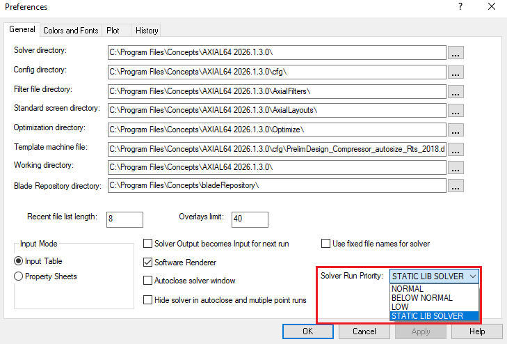
Updated capability to load custom startup scripts from locations outside the installation directory. This includes multiple user-defined macro lookup folders, convenience buttons and fixes to the macro function signature to assist UI navigation errors.
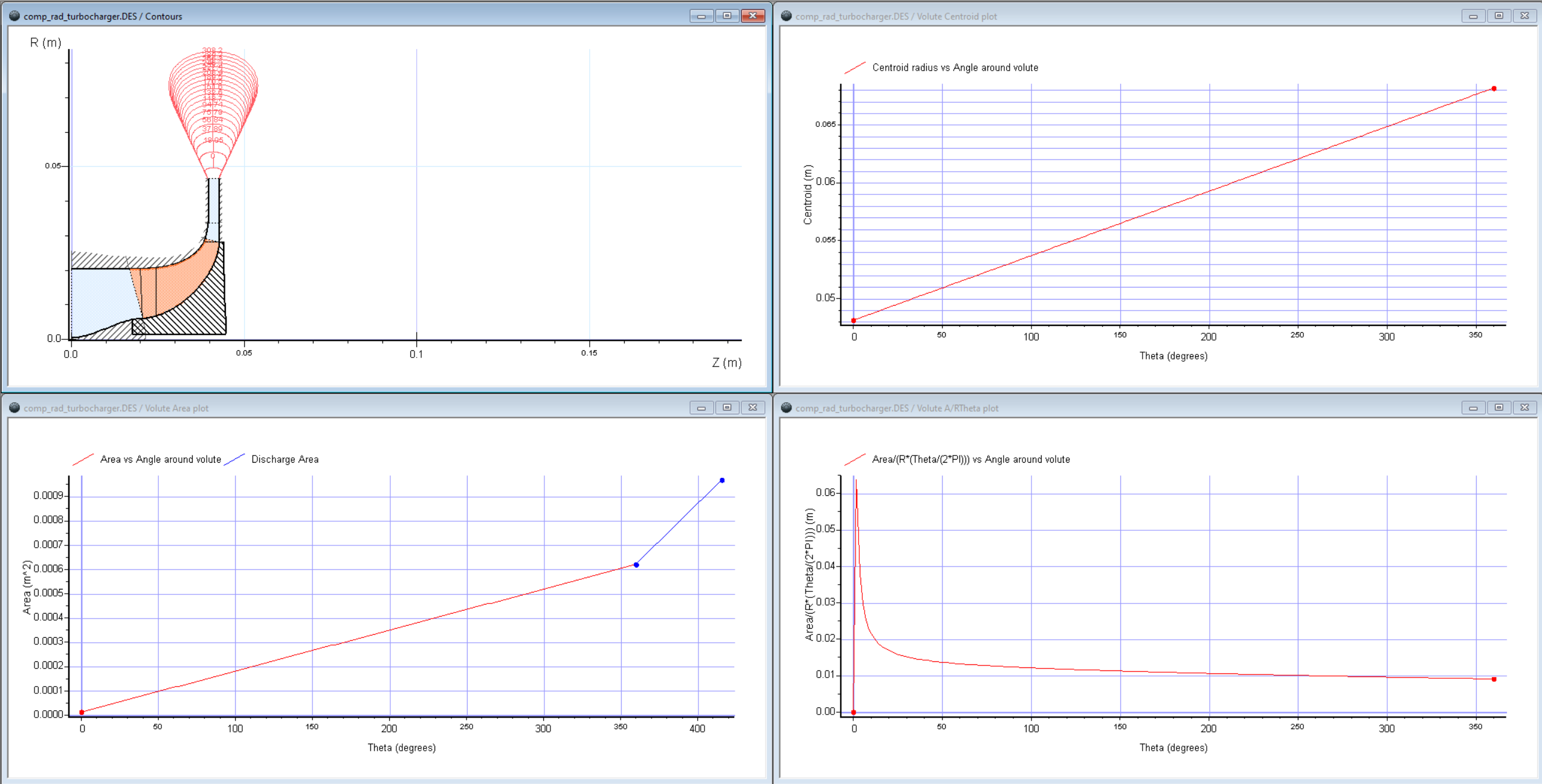
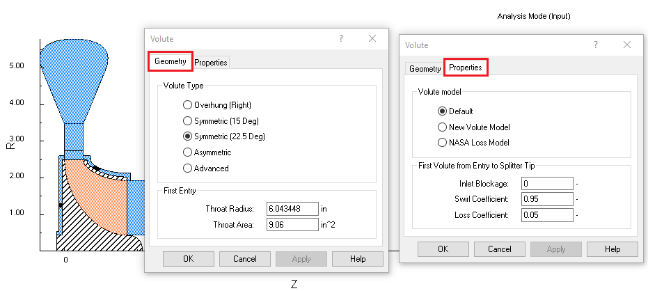
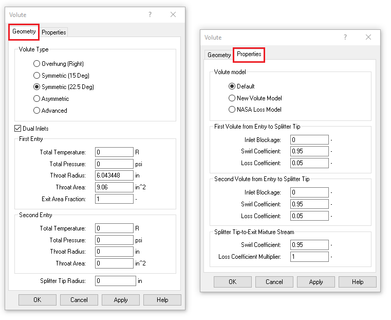
Introduced several improvements to the volute modeling workflow to provide better insight into geometry, improved visualization, and faster performance:
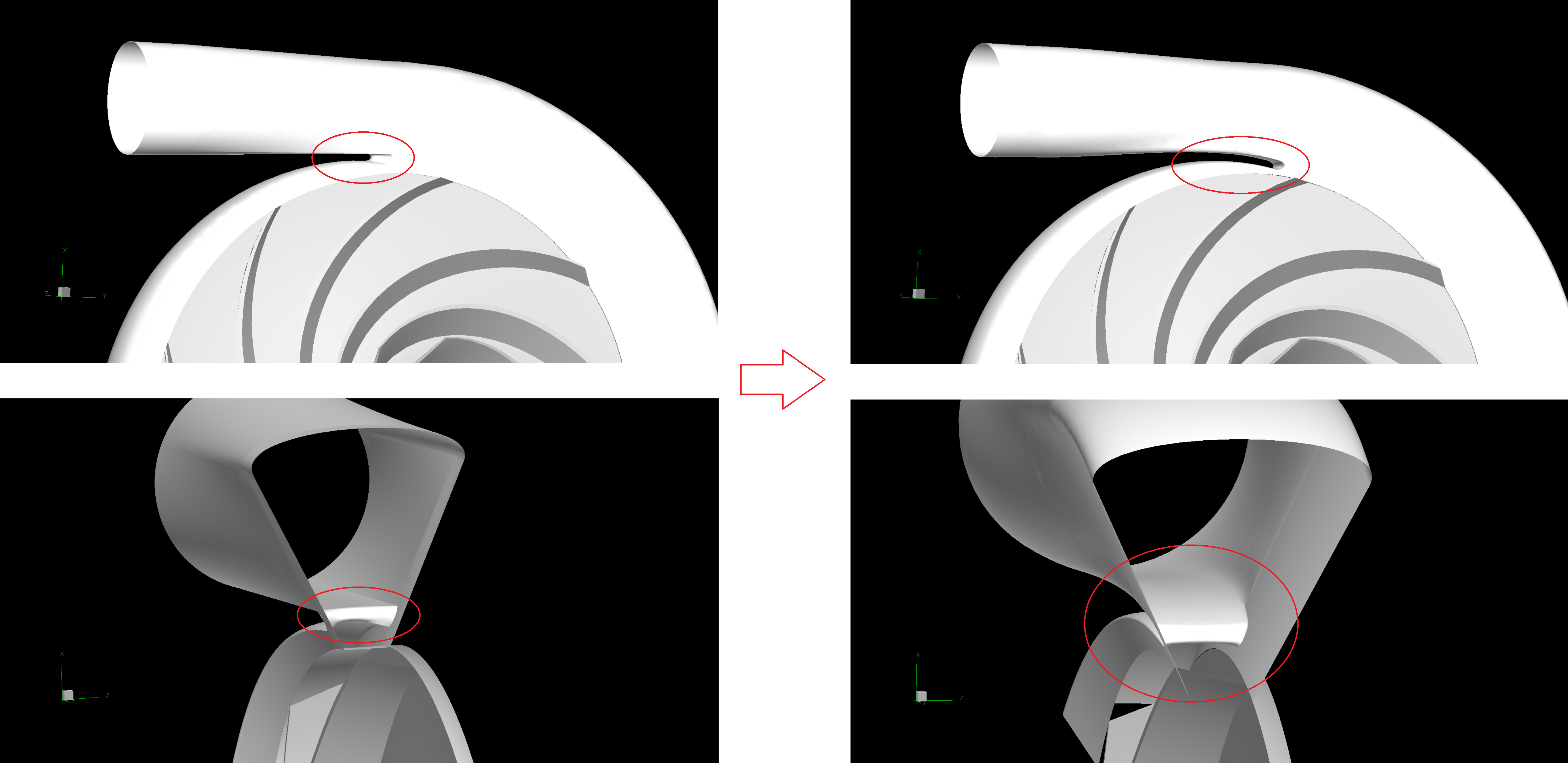
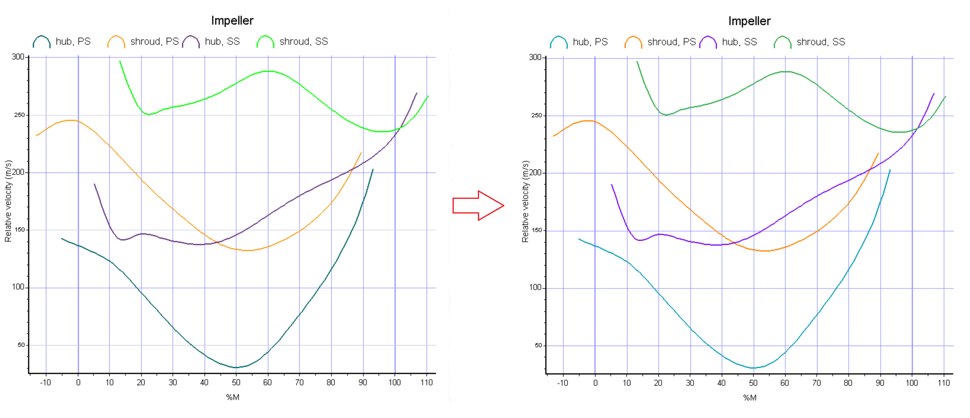
Improved color scheme for suction surface hub/shroud and pressure side to enhance visual distinction.
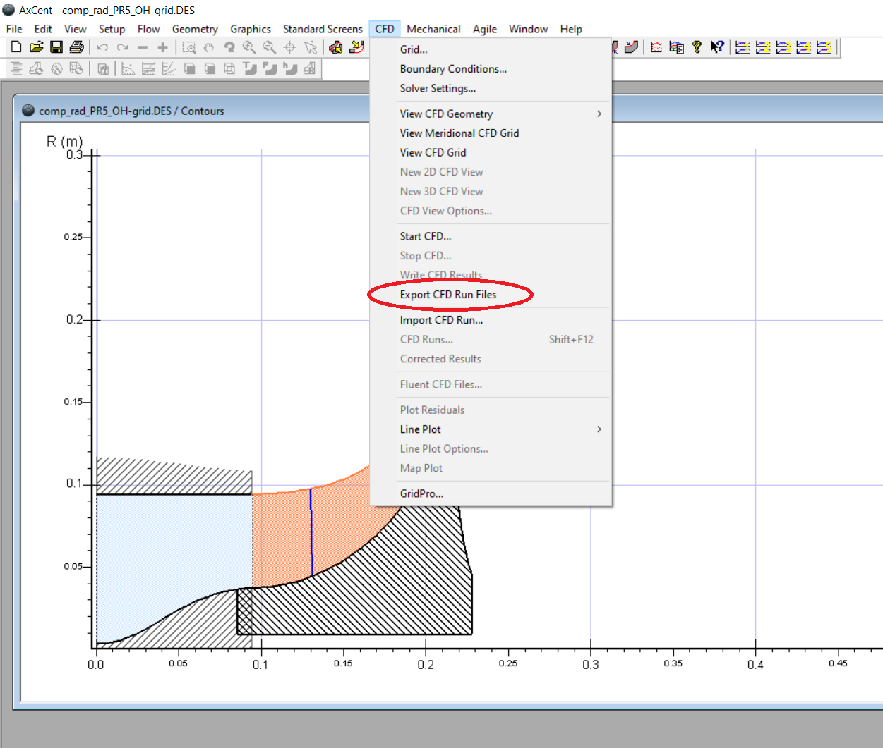
Added Export CFD Files command to generate all required workflow files up to the point of run submission (without actually launching the solver). This lets you fully stage CFD jobs, verify inputs, and hand off complete run directories to remote clusters or automation scripts, improving repeatability and reducing setup time.
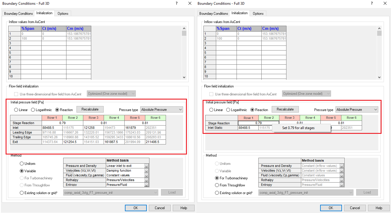
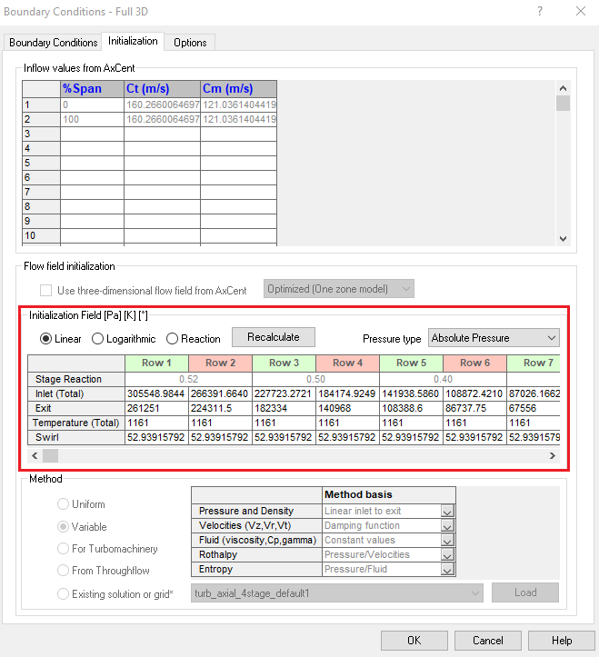
Added per-stage reaction controls for initial pressure distribution when setting up multi‑stage CFD runs. Instead of relying on a linear or logarithmic pressure distribution with a uniform degree of reaction, you can now specify the reaction for each stage explicitly. This allows more robust initialization for compressors and convergence for compressors with many stages. Also added a right-click option to set a constant reaction value for all blade rows.
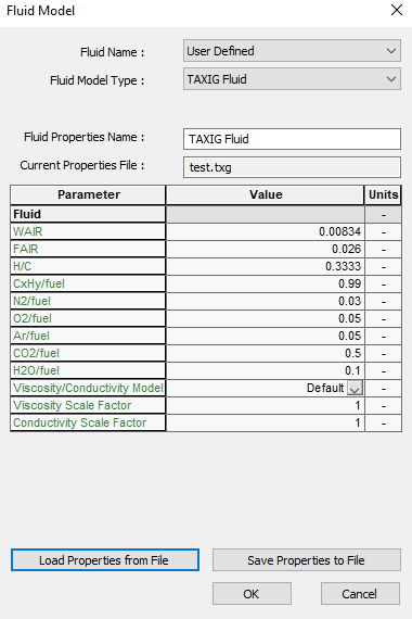
Semi‑Perfect Air fluid model is now fully integrated into the standard CFD workflow for both Code LEO and Ansys CFX. You can select Semi‑Perfect Air directly during case setup and carry it through meshing, solving, and post‑processing without manual file edits, improving consistency and reducing setup effort for compressible air applications.
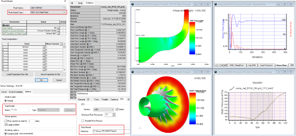
Real Gas fluid model is now fully integrated into the standard CFD workflow for Ansys CFX. You can select fluids from NIST 10.0 directly during case setup and carry it through meshing, solving, and post‑processing without manual file edits, improving consistency and reducing setup effort for compressible air applications.
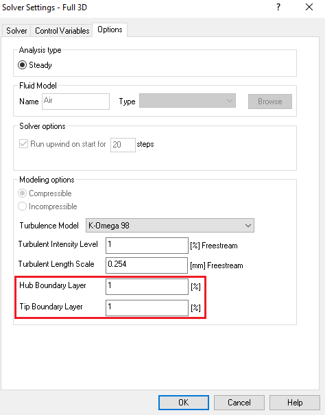
The previous single “BL thickness” setting has been split into two explicit inputs for hub and tip boundary layers (HBL and TBL) in the Solver Settings dialog. This gives you independent control of hub and tip boundary-layer thickness assumptions across multiple blade rows, improving model fidelity in cases with asymmetric endwall conditions.
Improved the BC Initialization workflow for ADS Code LEO by adding total temperature (TTIN) and swirl angle (ALPIN) to the initialization table, alongside the existing total pressure input. For the first row, initialization values now use the boundary‑condition inputs directly from the BC tab. For downstream rows, AxCent automatically constructs a minimal inlet span profile (0% and 100% span) with consistent P, T, and swirl values and computes pitch (PHIIN) from the local hub and shroud wall angles. These changes provide LEO with the required total conditions for robust startup while reducing manual data entry and the risk of inconsistent initialization across stages.
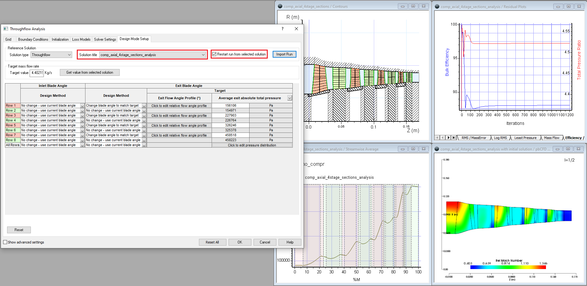
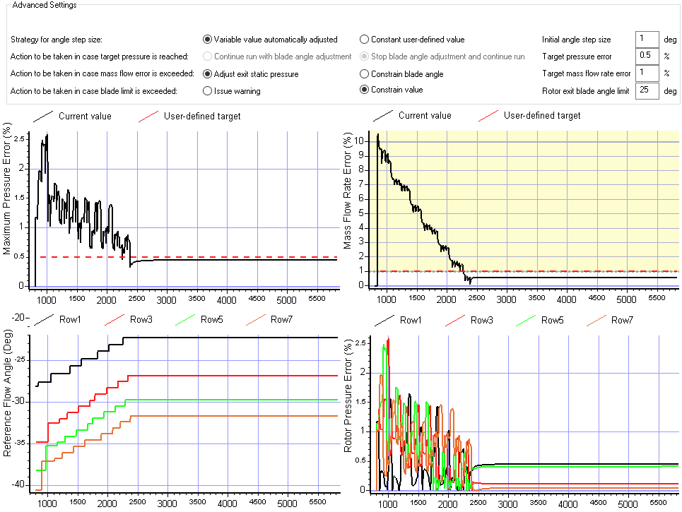
Expanded design capabilities to support stage pressure and mass flow targets. Added enhanced convergence tracking with additional in-run plots (e.g., mass flow error, pressure error, reference flow angles). Enabled restarting runs from previous analysis or design mode solutions.
Added gouge checking of flutes with part for surface milling. On the Orientation tab of Surface Milling operations. This enables users to set a gouge tolerance where anything greater than this is reported as a gouge and will return an error.
Added support for more tool types in surface milling flank orientation such as bull endmills, flat endmills, and nose endmills. This gives the user more flexibility when using the flank orientation option.
Updated collision checking to include the full SREV definition. This allows users to include other 2D revolved geometry in addition to the shroud and hub.
Added support for undercutting with lollipop tools and disc cutters in 3+2 roughing operations. This allows for increased material removal in each tool orientation, reducing the number of times the part needs to be repositioned.

Expanded 3+2 configuration stock to include edge and shroud offsets. This provides more consistent depth of cut and step over results and prevents the tool from plunging into stock at the edges and shroud when stock has been added to the automatically generated revolved stock model.
Included surface of revolution from geometry configuration in 3+2 part model to provide more robust collision avoidance.
Updated 3+2 rest stock STL file output location. Files will now be output to the RestStock folder to keep the main working folder more organized and clean.
Fixed perimeter approach move to match previous versions. The addition of partial boxes for perimeter passes negatively affected the toolpath shape when using full perimeter passes. This has been fixed so that toolpaths from older versions will generate the same when opened in new versions going forward.
Improved insert and retract moves to better handle changing start position and blending. Insert and retract moves are now closer to the start and end positions of each pass instead of working from the middle of the cavity, producing a more efficient toolpath with less air cutting.
Added new method spiral roughing to MAX-SB operations. This allows for plunging the tool into stock when the part does not allow for entering from the tip of the blade such as when the part is shrouded or is supported by a tailstock.

Added new method to Edge and Blade Finishing toolpaths to which allows cross-flow toolpaths to extend through the fillet and onto the hub by a specified extension distance. This allows for users to eliminate cusps and mismatches caused by fillet finishing toolpaths at the leading edge.

Added new Mixer function to add enable writing comments to the APT output when using the Freeform method. This can be done by adding the word “remark” to the start of a line. Anything following that remark will be written to the APT file.
Added support for basic APT formatting in Mixer. The standard APT formatting options such as removing comments or block numbers can now be specfied for Mixer operations on the NC Output tab by clicking the APT button.
Improved Mixer FOR loops to support math with the indexer i.
Updated clipping plane view so that it stays active after closing the window. After defining a clipping plane, click “OK” to close the dialog and keep the clipping plane active. To turn off the clipping plane, open the dialog again and click “Done.” This enables users to work and simulate with the clipping plane active without the dialog getting in the way.
The values used to define the plane are also remembered so that it is easy to make small adjustments after closing and reopening the dialog.
Added a new diagnostic option to calculate the resulting blade surface deviation when the blade is defined using surfaces. This helps ensure that the configuration is accurate and allows the user to easily figure out how many sections are needed. This setting can be found by double-clicking on the geometry configuration, and clicking the Diagnostics button.
Updated the blade definition dialog to allow users to delete sections from tabular data. This can be useful when the tabular data file has extra sections that are not needed in MAX-PAC. Deleting the sections in the UI will not remove them from the input tabular data file.
Added a new "Active" configuration option to the geometry configuration toolbar. When working with multiple configurations, this allows users to set an active configuration so that any new operations created will use the Active configuration, preventing the user from having to set this value multiple times for every operation created.
Improved tool library column functionality so that custom column widths will be remembered when the tool library dialog is closed and reopened.
Updated how CTI and TLS files import tools to allow for more robust import of libraries.
Improved how the tool 2D profile is trimmed, enabling more robust tool modeling.
Added the ability to plot linear axis reversal points in simulation. This includes defining axial and rotary offsets which enable users to more accurately plot XYZ reversals and approximate where the reversals will actually occur when posted to the machine coordinate system.
Added a new interface to the Machining Setup Properties menu for customizing process documentation including selecting custom setup images, customizing the columns, and switching between HTML and TXT output types. This makes it easier to customize the process documentation and produces a more consistent output when exporting the document. This dialog can be found by double-clicking on “Setup sheet” in the Properties node in the Machining setup.

Improved setup sheet column customization by allowing the user to customize which columns are included in the UI instead of editing CFG files.
Improved the TXT output format to include a separate tool table text file when TXT format is selected.
Added options to show tool technology parameters in setup sheet tooling tables such as Manufacturer or Flute number.
Updated tool 2D sketches in the setup sheet to include the shoulder diameter dimension.
Improved drag and drop functionality to show a line where the operation will be inserted when the cursor is released.
Updated operation info table to enable customization of the columns in the UI instead of editing CFG files. This can be done by right-clicking on the column names in the table and clicking “Edit columns.”
Updated cycle time formatting in the operation info table to show cycle times in hours and minutes instead of just minutes.
Improved SRI file import to make it more robust such as properly setting the file naming in the NC Output tab and ensuring the depth method is set correctly.
Launch of our new preliminary design and scoping tool, ParaScope, offers a map-based approach to scoping your pump design. In Beta, this tool is a quick entry point to scope a machine before moving into higher fidelity analyses in our meanline and AxCent tools. Initially released for pumps, we’re eager for user feedback.
Full expansion of our Python API to both COMPAL and PUMPAL, inclusive of both design and analysis modes. This API enables users to create custom templates for radial machines, set up a repeatable process for tuning to CFD results, incorporate our solvers into custom scripted processes, enable users to leverage AI and machine learning during the meanline design process, and more.
Our upcoming webinar will cover the current functionality as well as demonstrations of usage. Sign up today: Events | Concepts NREC
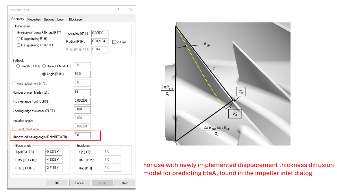
Implemented a new impeller diffusion model proposed by Concepts own, Kerry Oliphant. This improved hybrid model for modeling impeller diffusion with the two-zone model is based on Reynolds number, blade blockage, blade length before the throat, blade turning before the throat, the direction of the turning, and whether the impeller is covered or uncovered. Turning angle has been added as a field on the impeller inlet geometry page, defaults provided.
Easier navigation with colored toolbar icons in COMPAL, PUMPAL, and RITAL. Additional updates to user experience intend to make navigation clearer.
![]()
We’ve added an implementation for estimation of maximum mass design mass flow rate to address errors that occur when an unrealistically high flow rate is specified. With the fix, the application no longer crashes in these scenarios and instead handles invalid input gracefully.
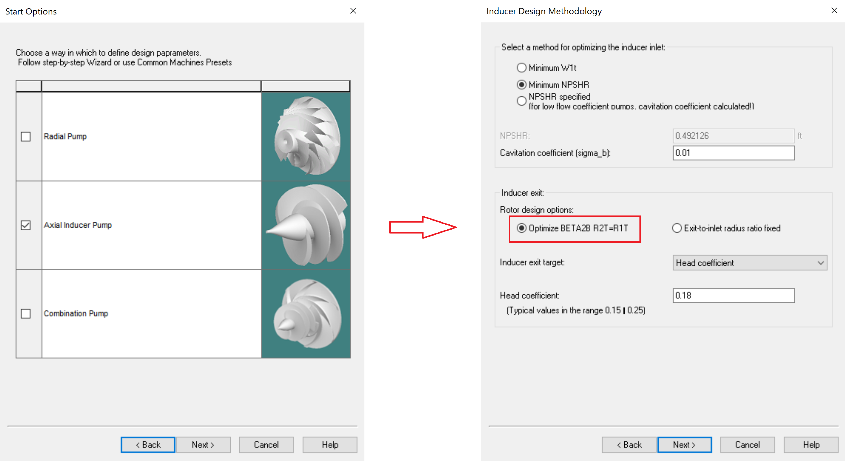
Inducer and combination pump templates now default to using the Optimizer Beta2B rotor design option for Inducer exit, with a matching default value for Head Coefficient. This update aligns with the recommended default inducer head settings and follows underlying fixes that improve the reliability of the head coefficient target/optimization behavior for axial inducers and combination pumps.
Concluded development work to improve dialog accessibility in RITAL. Updates condense properties and options tab when applicable and dynamically show/hide dependent fields for clearer indication of available parameters in your design.
We’re introducing a revamped integration between our workflow automator and optimizer, TurboOPT II, and Ansys optiSLang for easier integration of Concept’s software in optiSLang optimizations. Inputs and outputs are automatically ported from TurboOPT II to optiSLang for easier, quicker, project setup.
Introduced quick limits to your output parameter project setup to quickly assign ranges to output parameters of interest reducing project setup time.
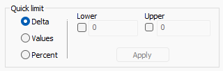
Refreshed quick range during input parameter setup for easier setup of input parameter ranges using percentages, deltas, or exact values.
Easier navigation with colored toolbar icons in TurboOPT II. Work mirrors COMPAL, PUMPAL, and RITAL for consistency.
Introduced warnings for project setup with third party optimizers to ensure proper input/output parameter definition with optiSLang and modeFRONTIER. Especially for derived parameters or customer expressions, TurboOPT II will provide a warning message if setup is incompatible with your selected third party optimizer, saving time and reducing errors in setup.
Misc.