What is 5 axis machining? In short, it is manufacturing a component on a CNC milling machine that can travel in 5 different directions. These machines allow the cutting tool to reach around parts with a high degree of freedom. This makes them ideal for milling the complex shapes of turbo machinery components.
Machine Configurations
While there are many variations of multi-axis milling machines, we’ll focus on the of 5-axis machines that are commonly used for cutting turbomachinery parts.
A basic example 3 axis milling machine holds the tool vertical and moves it in X, Y, and Z directions. In this case the X and Z axes move the tool and the Y axis moves the part, but the resulting tool motion relative to the part forms a right-handed coordinate system. The Z axis generally matches the tool axis.
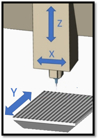
Image 1 – 3 Axis Mill
To this 3-axis configuration we can add two rotary axes, giving a total of 5 axes. The rotary axes are typically labeled A, B or C depending on the respective linear axis X, Y, or Z they rotate about. Each rotary axis may move the tool or part, but the goal is to allow any orientation of the tool relative to the part. While it is possible to retrofit a 3-axis machine by bolting on rotary axes, many machine tool makers offer dedicated 5 axis configurations.
Image 2 shows a trunnion style of machine which has become quite popular. The A axis tips the part and the C axis rotates the part. Depending on the machine builder, the tipping axis could also be labeled B if it tips the part about the machine Y axis. Note that the part can easily be fixtured on a horizontal surface. Also, the part can be fixtured so that its center of mass lies roughly on the A axis centerline, reducing rotary torque forces required.
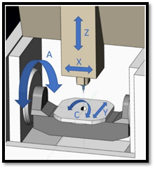
Image 2 – Trunnion Machine
Image 3 shows a tilting spindle machine. The B axis tips the tool and the C axis rotates the part. This setup helps for larger parts since the part does not need to be dynamically tipped, though the tilting spindle loses some rigidity.
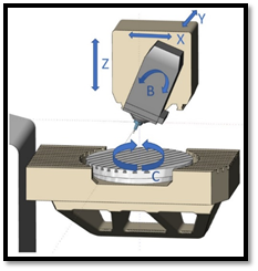
Image 3 – B axis swinging head
Image 4 shows a gantry machine. The 2 rotary axes sit at the end of the Z axis ram, which is mounted on a moving bridge construction. These machines are well suited for large components that are too heavy to mount on a rotating table and swinging head.
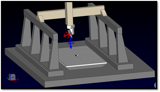
Image 4 - 5 axis Gantry CNC
A Nutating machine is a compact 5 axis machining center where one of the rotary axes moves in a non-orthogonal system. In Image 5, note the yellow rotary centerline 45 degrees from vertical. With this configuration the tool orientation relative to the part is limited, which can prevent milling fully around a blade. However, adjusting the angle of the yellow vector can extend the capability. Image 5 shows the rotary axes both moving the part, but nutating machines may also have rotary axes that move the tool.
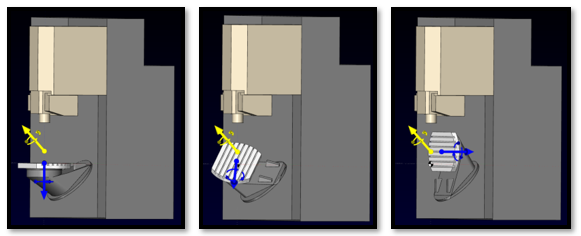
Image 5 - Nutating machine in three rotary positions
Software for 5-axis milling
All of the 5-axis kinematic configurations can make toolpath programming difficult, but fortunately software solutions have kept pace with the developing technology.
CAM (Computer Aided Manufacturing) systems offer various multi-axis cutting strategies to utilize the flexibility of 5-axis machines:
With 3+2 machining we position and lock the rotary axes before cutting. This gives a rigid setup for heavy cutting. Planar roughing levels give more consistent cutting conditions and chip thickness for faster cutting. 3+2 machining can also allow faster feeds because the rotary axes are often the feed-limiting factor during 5-axis cutting.
4+1 machining positions one of the rotary axes to a fixed position. This may be desirable to eliminate unwanted motion of one rotary axis, though it may require more motion of the other rotary axis to avoid tool-part collisions. 4+1 programming is also of course useful if there is no 5th axis on the machine.
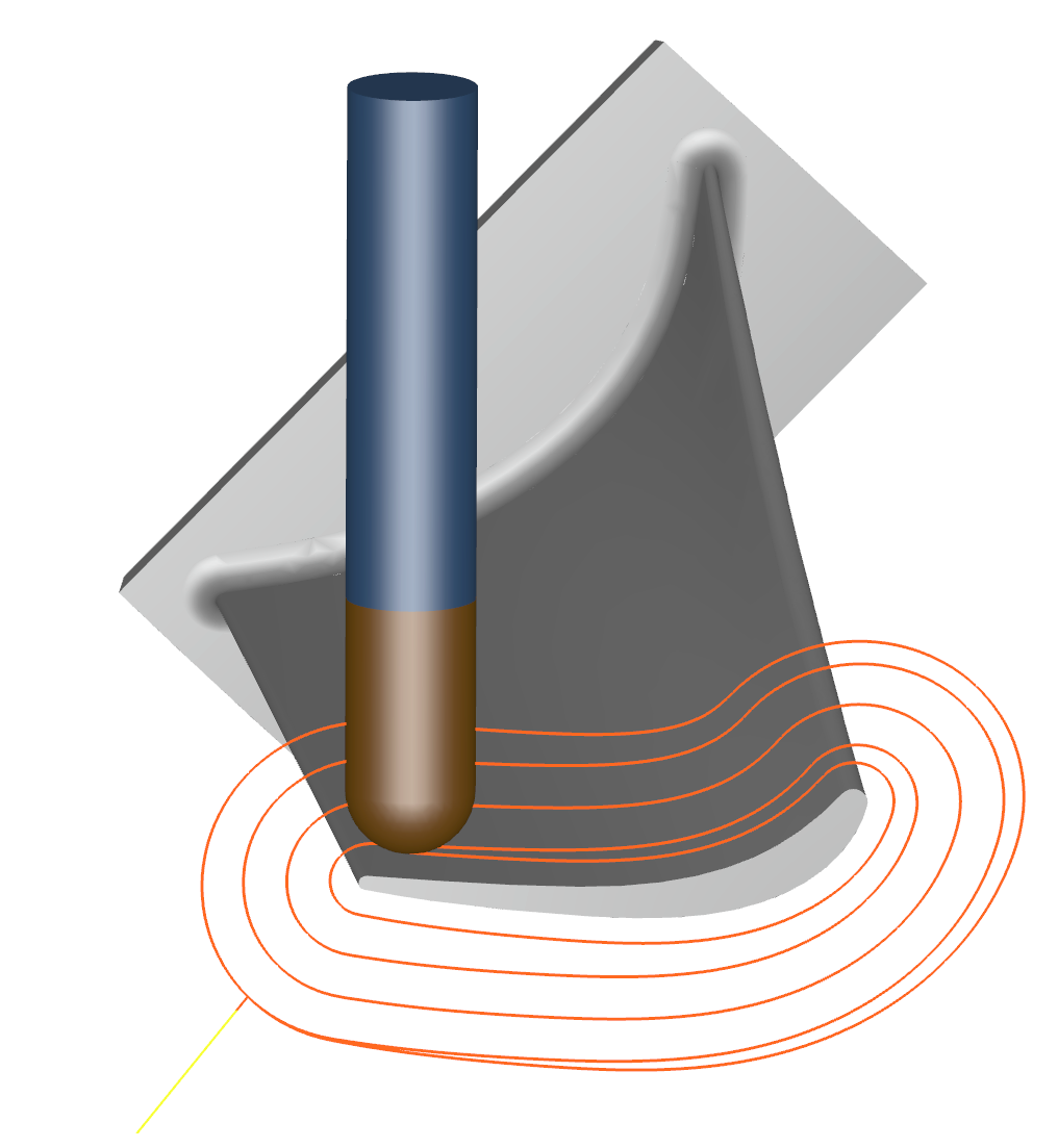
5 axis simultaneous motion is a necessity for turbomachinery components. All 5 axes move at once to guide the tool around the blades and through the pockets without collision. This allows smooth uninterrupted cutting for both roughing and flowline finishing. Newer machines with torque-motor rotaries allow high-speed 5 axis cutting.
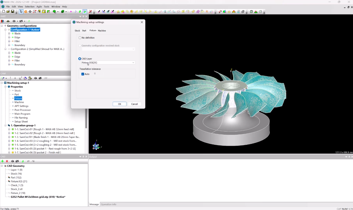
Modern CAM software can also simulate the 5-axis machining process. This allows clear visualization of the complex machine motion with reports of collisions, overtravel (stroke limit) conditions, and other potential hazards. Programmers can easily confirm that the part, fixture, tooling, and milling machine are all safe and suitable.
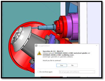
Image 6 – Machine Simulation detecting collision
Most new CNC machines offer TCP / RTCP (Tool Center Point / Rotating Tool Center Point) mode. This is an optional function within the machine controller that is designed to keep the cutting portion of the tool in constant straight-line contact with the workpiece. Without TCP, the tool tip can make a damaging scalloping motion between commanded 5-axis positions. TCP simplifies the CAM system’s postprocessing job because the commanded XYZ values are in workpiece coordinates and the machine controller calculates the XYZ axis values. The toolpath files are thus more generic and versatile, so they can more easily be transferred from one fixture setup to another, or even from one machine to another. The machine operator can easily make any necessary adjustments to the workpiece reference origin while eliminating the need to repost the operations. Without TCP, the toolpaths may have hard-coded offsets for a specific fixture setup. TCP also makes feed programming easier. Just one feed command is needed and the control maintains the tool tip speed relative to the workpiece. Without TCP, non-intuitive inverse-time feeds must be programmed on each line.
At Concepts NREC we have a broad audience of turbomachinery specialists. If you’re in manufacturing then this summary may be remedial, but for others we hope it provides some insight and encourages you to take stroll down to your machine shop or visit the vendor where your parts are made.
If you have any questions or comments, please let us know in the comments section below or contact us at info@conceptsnrec.com.