During the compressor design process, one of the key optimization steps is to adjust the impeller exit blade angle with the goal of achieving the desired pressure ratio, efficiency and range.
When we consider the fundamental relationship of impeller work, using Euler’s turbomachinery equation for specific work (Figure 1), we can see how the impeller blade exit angle has a direct impact on the impeller work through changes in the impeller exit absolute tangential velocity, CƟ2. Based on this equation, you might think that having pure radial blades is best, since radial blades allow for more work to be performed (for a fixed impeller exit radius), leading to higher pressure ratios. Unfortunately, there is a downside….
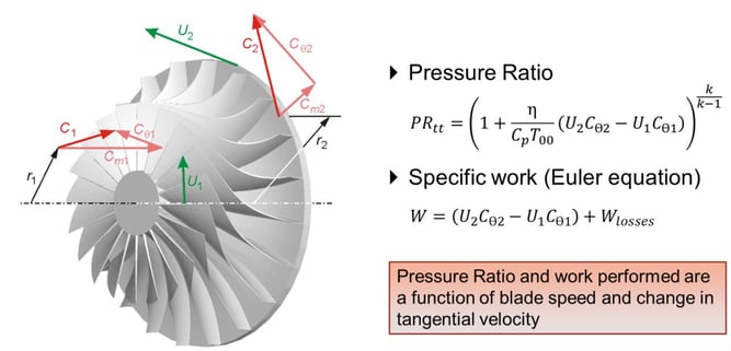
Figure 1. Impact of Impeller Velocity Triangle on Pressure Ratio and Work
Consider the velocity triangle at the exit of the two impellers shown in Figure 2. On the left (no backsweep – β2 = 0), when flow is increased (increasing W2 from top to bottom), UCƟ remains unchanged. As a result, the pressure ratio and specific power remain unchanged with flow rate under idealized conditions. When backsweep is introduced (on the right), an increase in flow has a significant impact on the velocity triangle, decreasing UCƟ when flow is increased. As a result, the impeller with backsweep will exhibit a higher pressure ratio at lower flow. This results in a steeper slope of the head-flow curve for the backswept impeller compared to the pure radial impeller as illustrated. A steeper characteristic generally leads to improved flow range and more stable operation.
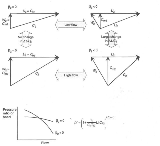
Figure 2. Comparison of radial and backswept blades under idealized conditions
In addition to the general behavior of the head-flow curve, backswept blades have a profound impact on efficiency. Let’s consider two impellers with the same meridional velocity and power (Figure 3). Because the power is the same, UCƟ must be equal. To achieve this, the backswept impeller must operate a higher U given its lower CƟ. While the backswept design will have higher tip speeds (and hence higher stresses), it will also have reduced absolute kinetic energy leaving the impeller (lower C2). This reduction in kinetic energy leaving the impeller yields a lower kinetic energy entering the diffuser, reducing diffuser losses. In summary, backswept impeller blading is used to extend range and improve efficiency, but with a penalty of increased stresses.
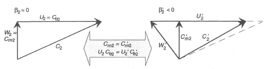
Figure 3. Impact of backswept blades on the compressor tip velocity triangle