Why Meanline Scripting is Becoming Essential for Turbomachinery Design
Manual meanline design can sometimes feel less like design and more like managing a chain of tiny decisions.


In many instances, the design of new turbofan engine is an iterative process of optimizing engine cycle parameters (i.e. thermodynamics) and executing preliminary design geometry of engine components (i.e. aero design, constrained with structural, manufacturing, fitting in engine layout, size, weight & other requirements) for the best performing realizable solution. Consideration of the preliminary design of the engine in the totality of these requirements seems to be an interesting topic to address.
Coupling cycle calculations with detailed preliminary design of turbomachinery components for getting optimized turbofan engine is the topic of this article. Detailed preliminary design means generating geometry and getting flow data and performance for each component of the multistage geometry of the engine, sufficient in the scope to move design process to 2D and 3D considerations.
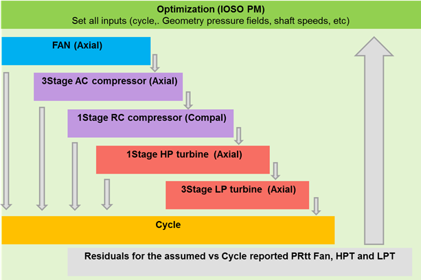
Let’s consider a model of a two-spool turbofan engine, with layout F1-A3=R1= HPT1-LPT3 configuration (i.e. 1stage Fan, 3 stage Axial compressor, 1 stage radial compressor, 1stage high pressure turbine and 3 stage low pressure turbine). This configuration is quite similar with engine configuration in applications of large UAV and small business jets.
For start, each of the turbomachinery components in the engine layout is set as a template file in redesign or preliminary design mode (of course, using Agile Design system by Concepts NREC), so that geometry can be modified by controlled via general sizing parameters and streamwise distributions of non-dimensional radial sizing, areas chords, solidities, distributions of pressure fields, with each blade row to be controlled by optimizer. Each blade row in axial machinery, and radial impeller and each element of diffuser system in radial stage are set to be completely flexible in regard of flow conditions, pressure ratio splits, reaction with the geometry to fit these requirements. The calculated entities are of course performance data, needed to run cycle calculations, geometric dimensions and weight, evaluated based on sizing of individual blade rows.
A cycle code, which uses the predicted performance data for turbomachinery components and assumed modeling parameters for combustor, mechanical shaft losses and cooling flows, mixer, etc. is set to evaluate engine performance. GasTurb© maybe a possible candidate for a cycle code, but other options can be exercised.
Since assumptions on input conditions to get turbomachinery geometry and performance data may not match the cycle code results (for example - assumed exit pressure of the fan stage may not match the balanced engine cycle requirement), design inputs for turbomachinery components for the engine and the cycle outputs must be resolved for a fully balanced outcome. In the current approach, the optimizer is used to handle this resolution, though it is not the most computationally economical approach.
The ultimate design problem is to get optimized engine geometry, therefore an optimization process must be formulated to keep turbomachinery and cycle parameters adjusted for the best SFC, while meeting restriction for aero and structural design rules, fitting sizes in reasonable engine layout/proportions, meeting requirements on metal wall temperatures (cooled or non-cooled, including variation of cooling flow), with consideration of estimated engine weight.
To achieve that the following automated pipeline of the design process is assembled, using Axial™ for design of fan, axial compressor and turbine stages, using Compal© for radial stage, a proprietary cycle code and IOSO-PM optimizer:
The following formulation of the optimization is considered in the explored case:
Optimize Engine sizing for best SFC in the interest domain for the Thrust:
- objectives:
- SFC (minimize) vs Thrust (maximize to the specified limit value)
- variables:
- flow path sizing of each turbo-machinery component
- flow-path dimensions (controls bypass ratio)
- blade parameters (angles, chords, solidities)
- PR and reaction splits (stages & blade rows)
- spool speeds
- Fan geometry split – by-pass ratio
- Engine inlet mass flow and temperature at combustor exit
Use models and rules/constraints:
- aerodynamic loads and stalling criteria:
(hub, mean tip, where appropriate)
Zweifel, D-factors, Stalling effectiveness …
- Structural limitations:
AN2, Rh/Rt, Uh (disk rim speed)
- Thermal limitations:
- Metal surface temperatures cooled HPT nozzle and rotor
- Manufacturability:
Blade separations, blade chords, blade heights …
- Engine layout requirement:
Max radii ratios - fitting turbomachinery components in engine layout
minimum Rh (rotor dynamics …)
- Evaluation of cooling effectiveness per varied cooling flow to the blades
- Evaluation of weight, radial and axial sizes (based on each component/blade row)
Restrictions and design rules are the only set requirements in this design pipeline, with expected outcome of optimized engine designs as a Pareto line representing design tradeoffs between SFC and Thrust – i.e. the result of optimization is a family of engines, so that design engineer can select the best possible compromise solution.
The optimizer offers flexibility in the problem formulations, for example – designer request tradeoff solutions in metrics SFC-Weight at the given level thrust
In this demo the set optimization showed the following metrics:
Number of input variables: 75
Number of Outputs: 200
Number of Constraints: 100
Number of Objectives: 2 (minimize SFC, max Thrust)
Number of runs/considered geometries: >350K (that could be significantly improved with adding explicit resolution of residuals between assumed for design tools and predicted pressure ration by cycle code).
Given number of constraints, some of which very nonlinear (for example - stalling restrictions for compressors) and number of used inputs it is a formidable problem for any optimizer. Luckily, IOSO optimizer that we used in this example proved to be up to the task.
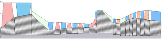
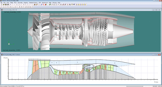
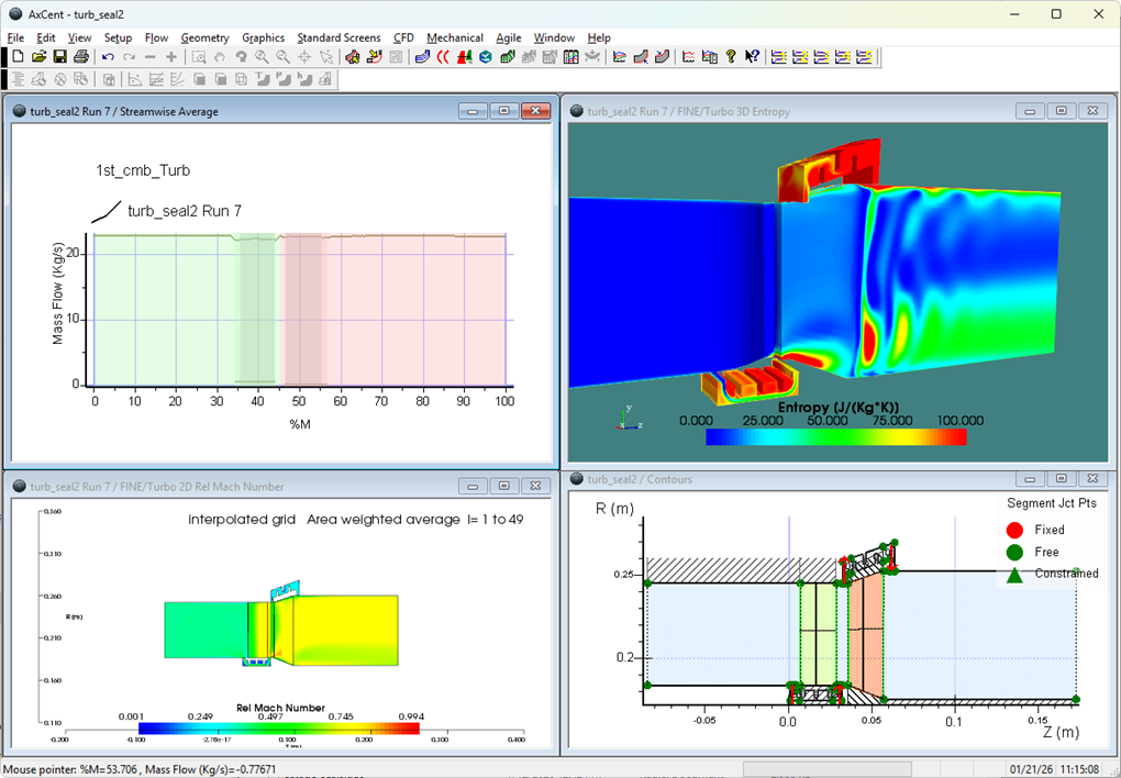
Executing calculations for a quite common thrust requirements (to be in range similar with PW 500 engine series ) produces the following results with this visual preview in preliminary design tools:
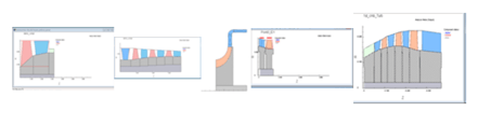
These can be assembled in “meanline” and “initial 3D” layouts in Axial™ and Axcent©:
In the process of setting and solving this example, a set of separate optimizations was executed for individual components of the flowpath with interesting observation - some of the individually optimized turbomachinery components for frozen operating conditions showed better performance, vs performance reported in the globally optimized results. However that does not indicate possibility of further engine improvement, as these individually optimized components violate engine cycle balances and there is system effects of tradeoffs in the globally optimized engine - the changes in any one component of the engine force changes in the rest of the engine components to retain balanced engine design. That tells that “improving” engine with uncoordinated “optimization” of individual components of the engine, without systemic engine rebalance, may not necessarily lead to increase in engine SFC.
For example, in this case HPT reported total-to total efficiency ~ 84.5% in optimized engine, while standalone optimization would show potentially achievable ~ 86.5%. During engine global optimization such high efficiency geometries were considered, but never accepted in the SFC-optimized sets.
Additional checks showed that increase HPT efficiency dictated higher shaft gas-generator speeds, which caused redistribution of PR between HPT and LPT in such way, so that redesigned (and individually optimized) fan stage comes with performance penalty. Since HPT works on internal bypass mass flow, which is a fraction of external flow, providing smaller contribution to thrust (and SFC) vs larger fraction of flow in the fan, it appeared that excessively high HPT efficiency is penalizing factor for engine SFC.
Such tradeoff between engine components is easy to miss when cycle and preliminary sizing of the turbomachinery components are not coupled.
Tags: CAE Software, Engineering

Manual meanline design can sometimes feel less like design and more like managing a chain of tiny decisions.

For most turbomachinery engineers, optimization isn’t a new idea. It’s a critical part of their workflow that can’t be overlooked. But sometimes that crucial step isn’t easy to get to.
It’s no secret that turbomachinery design has been one of the most demanding CAE environments, thanks to tight tolerances, complex physics, and long design cycles. That hasn’t changed in 2026, but...