Why Meanline Scripting is Becoming Essential for Turbomachinery Design
Manual meanline design can sometimes feel less like design and more like managing a chain of tiny decisions.


Designing turbines for low flow Rankine Cycle for steam is challenging due to their small size, manufacturing restrictions, clearances and cost constraints. Such turbines operate at significant pressure ratios that require use of partial admission and are likely to operate in choked supersonic flow mode due to reduced stage count (controlled by cost).
In such designs it is expected to have relatively low efficiency and a high sensitivity to manufacturing and cost constraints. It also makes overall cycle parameters dependent on the achievable turbine performance, which drives the need in early coupled considerations of the cycle and preliminary turbine design in the search of the best overall solution.
Using preliminary design tools which include optimization, such as the ones found in Concepts NREC’s Agile Engineering Design System®, can help solve these problems.
Let’s consider, as an example, a design task to find specifications for the most efficient simple Rankine power cycle with a Curtis Stage turbine, with the required electrical power output of 1.5 kW.
The problem formulation is as follows:
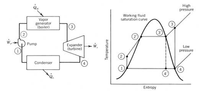
Modeling of the cycle, coupled with preliminary design of the turbine is set in a simplified way to replicate Rankine Cycle balances (flow, energy) in boiler, pump and turbine components, accounting for pressure loss in piping between pump and turbine, electrical generator electromechanical efficiency with evaluation of cycle electric efficiency. Cycle model includes function to automatically adjust inlet mass flow to deliver target electric power for the current turbine performance iteration.
Turbine model in Axial™ is set as a Curtis Stage turbine in redesign mode, that accepts inputs for stage radius, blade angles, admission(s), Laval nozzle area expansion ratio, rotor blades reactions, and pressure at exit of the 1st rotor - to calculate flow path dimensions for provided mass flow; inlet pressure and temperature, rotation speed - to construct flow path dimensions and calculate performance.
Constraints on the turbine design were imposed on aero performance (Zweifel coefficient, permissible flow diffusion at hub in rotor blades, hub reactions in rotors,), structural (AN2, maximum disk rim speed), manufacturing (limiting nozzle angles from extreme tangential values, minimum allowed blade height, minimum allowed throat blade separation distance).
The reasonable assumptions needed the cycle calculations forth following parameters:
Generator electromechanical efficiency
Boiler efficiency
Pressure loss between pump and Turbine
Pump efficiency
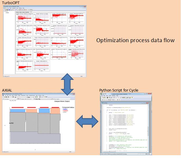
TurboOPT™, with an internal optimizer, is used to set and drive optimization. Simulated annealing followed by the Powel Method were used to execute the optimization.
The optimization problem includes 22 input variables (cycle and turbine design parameters), one objective for cycle electric efficiency (the second objective, electric power, is resolved by adjusting cycle mass flow automatically), and 14 constraints.
Adopted ranges for the turbine and some of the constraints:
Mass flow range: TBD from optimization
Inlet pressure range: TBD, < 20 Bar
Inlet temperature: TBD, < 450°C
Partial admission: 0.1 – 1.0
Rotation speed: XXXXX-XXXXXX RPM
Electric power: 1500 W
Max Zweifel numbers: <1.2
W2/W1 at hub of the rotors: >0.7
Rotor reactions (pressure) 0.02 – 0.07 (R1), 0.02 – 0.5 (R2)
Max Blade angles: <80° by magnitude
Exit swirl: -30 – 0°
Allowed range Laval nozzle area ratios: 0.6-1.0
Allowed blade heights: - per available manufacturing
Blade – casing clearances: - per available manufacturing
Minimum blade separation distance: - per available manufacturing
Stage RMS radius: 0.01-0.025 m
The flowchart of the optimization process and optimized solution is shown below:
Additional outputs from cycle model for the optimized solution:
Turbine aero power, kW 1.73
Turbine inlet mass flow, kg/sec - per optimization result
Pump exit pressure, Bar - per optimization result
Turbine inlet pressure, Bar - per optimization result
Temperature, °C - per optimization result
Electrical power, kW 1.50
R-Cycle ETA electric 0.10
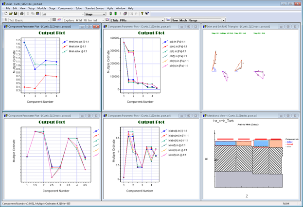
The optimized geometry of the Curtis Stage meets all manufacturing, aero and structural constraints with the following features:
It follows from the review of the optimization history plots and final solution, that most critical constraints, that affect the optimized solution in this example are:
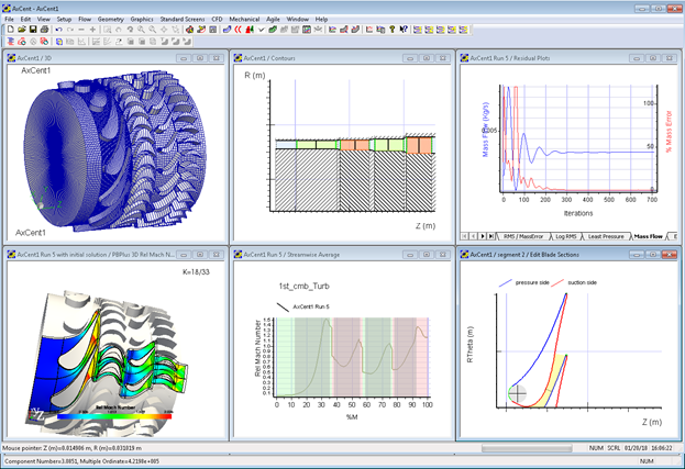
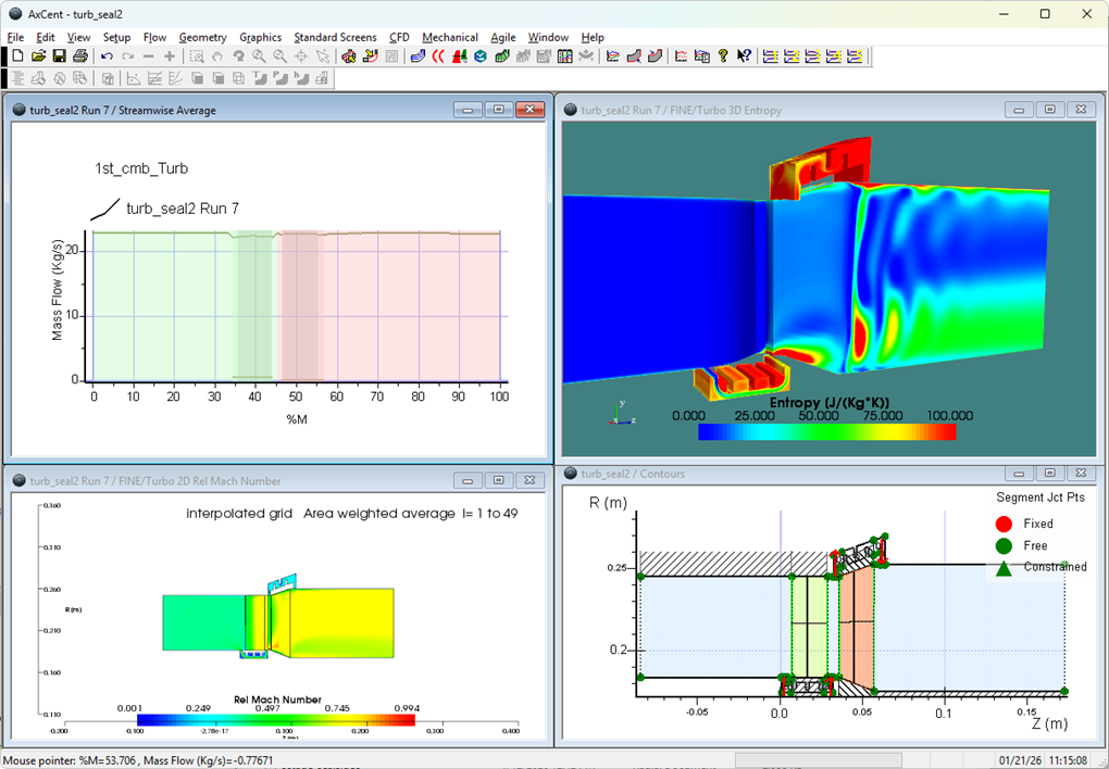
With the obtained results in preliminary geometry, the optimized turbine design can be advanced into AxCent™ for further 3D design and optimization. The unrefined 3D geometry, generated in AxCent directly from Axial, is visualized below (full admission view) and checked using 3D CFD:
The results demonstrate how the optimization process can be applied to the coupled consideration of cycle and turbine preliminary design, which delivers not only parameters for the best achievable cycle efficiency, constrained by turbine performance, but also produces turbine geometry and specifications, ready to be advanced into 3D design cycle.
Tags: CAE Software, Engineering

Manual meanline design can sometimes feel less like design and more like managing a chain of tiny decisions.

For most turbomachinery engineers, optimization isn’t a new idea. It’s a critical part of their workflow that can’t be overlooked. But sometimes that crucial step isn’t easy to get to.
It’s no secret that turbomachinery design has been one of the most demanding CAE environments, thanks to tight tolerances, complex physics, and long design cycles. That hasn’t changed in 2026, but...