Why Meanline Scripting is Becoming Essential for Turbomachinery Design
Manual meanline design can sometimes feel less like design and more like managing a chain of tiny decisions.


This blog article is a follow up for the earlier blog “Coupled Optimization of Preliminary Design Geometry of Low Flow Steam Turbine with Curtis Stage Layout and Rankine Cycle Parameters”, which considers more complicated case of coupled optimization of regenerative Rankine cycle and 2 stage turbine geometry with change from partial to full admission flow.
Let’s consider, as an example, a design task to find specifications for the most efficient regenerative Rankine power cycle for steam with a two stage turbine, with the required electrical power output of 1.5 kW. The first stage of the turbine is assumed use partial admission, while the second stage is to be of full admission.
The problem formulation is as follows:
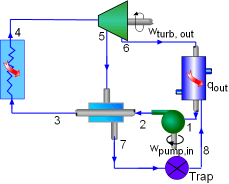
Modeling of the cycle, coupled with preliminary design of the turbine is set in a simplified way to replicate Rankine Cycle balances (flow, energy) in boiler, pump, regenerative heat exchanger and turbine components, accounting for pressure loss in piping between pump and turbine, turbine bleed and heat exchanger, heat exchanger heat loss to the environment, electrical generator electromechanical efficiency with evaluation of cycle electric efficiency. Cycle model includes function to automatically adjust inlet mass flow to deliver target electric power for the current turbine performance iteration. Turbine bleed parameters are fed into heat exchanger model, which is also part of the cycle calculations.
Turbine model in Axial™ is set as a two stage turbine in redesign mode, that accepts inputs for reference radius of the first stage and radius ratio of the second stage to the first stage, blade angles for all blade rows of the stages, admission of the first stage, Laval nozzle area expansion ratio of the first nozzle, rotor blades reactions for the stages, and pressure at exit of the first rotor (same as bleed pressure) - to calculate flow path dimensions for provided mass flow; inlet pressure and temperature, rotation speed - to construct flow path dimensions and calculate performance.
Constraints on the turbine design were imposed on aero performance (Zweifel coefficient, permissible flow diffusion at hub in rotor blades, hub reactions in rotors), structural (AN2, maximum disk rim speed), manufacturing (limiting nozzle angles from extreme tangential values, minimum allowed blade height, minimum allowed throat blade separation distance).
In addition to the available data on Generator electromechanical efficiency, Boiler efficiency, Pressure loss between pump and Turbine, Pump efficiency, Pressure loss in bleed to heat exchanger, additional input information is required for feed water temperature under-heating vs reference temperature of the steam bleed and heat exchanger heat loss to environment to proceed with regenerative cycle modeling.
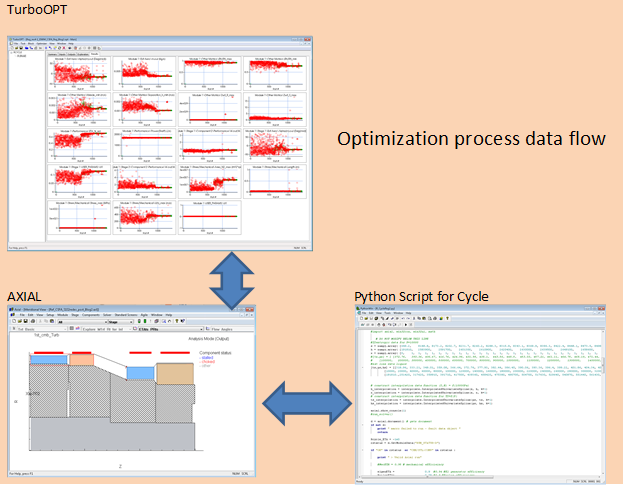
TurboOPT™, with an internal optimizer, is used to set and drive optimization. Simulated Annealing followed by the Powel Method were used to execute the optimization.
The optimization problem includes 22 input variables (cycle and turbine design parameters), one objective for cycle electric efficiency (the second objective, electric power, is resolved by adjusting cycle mass flow automatically), and 14 constraints.
Adopted ranges for the turbine and some of the constraints:
Mass flow range: TBD
Inlet pressure range: TBD, < 20 Bar
Inlet temperature: TBD, < 450°C
Partial admission: 0.1 – 1.0
Radius ratio stage2/stage1 0.6 – 1.4
Rotation speed: XXXXX-XXXXXX RPM
Electric power: 1500 W
Max Zweifel numbers: <1.2
W2/W1 at hub of the rotors: >0.7
Rotor reactions (pressure) 0.02 – 0.07 (R1), 0.02 – 0.5 (R2)
Max Blade angles: <80° by magnitude
Exit swirl: -30 – 0°
Allowed range Laval nozzle area ratios: 0.6-1.0
Allowed blade heights: -adopted per manufacturing technology
Blade – casing clearances: -adopted per manufacturing technology
Minimum blade separation distance: -adopted per manufacturing technology
Stage RMS radius: TBD
The flowchart of the optimization process and optimized solution is shown below:
Additional outputs from cycle model for the optimized solution:
Turbine aero power, kW 1.713
Turbine inlet mass flow, kg/sec - determined per optimization results
Shaft speed, rpm - determined per optimization results
Temperature, °C - determined per optimization results
Bleed fraction - 0.036
Bleed pressure, Bar - determined per optimization results
Bleed temperature, deg. C 257
Feed water deltaT in exchanger, deg.C 22.4
Electric generator power, kW 1.50
R-Cycle ETA electric 0.1203
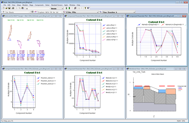
The optimized geometry of the turbine meets all manufacturing, aero and structural constraints with the following features:
Supersonic (Laval) nozzle with exit Ma ~1.7, with nozzle throat/exit area ~0.51 for fully expanded supersonic mode of operation (to minimize shock and transonic losses)
Choked flow is observed in all nozzle and blade rows (due to pressure ratio PRts >20 in low cost design with 4 blade rows)
Partial admission is of order 0.46 (to keep acceptable blade height and deliver best turbine and cycle efficiency)
RMS radius ration between stages is ~ 0.85, it helps to address blade height problem in transition from partial admission in the upstream stage to full admission.
Customized layout stage geometry and aero traits are delivered to achieve the best tradeoff between performance and meeting manufacturing constraints. For example, reaction of the first stage is close to zero (dictated by presence of partial admission and necessity to maximize nozzle expansion to meet minimum blade height constraints), while second stage operates at reaction level ~ 30% to improve turbine performance.
This solution can be compared against the previous blog article “Coupled Optimization of Preliminary Design Geometry of Micro Steam Turbine with Curtis Stage Layout and Rankine Cycle Parameters”, presented earlier.
These results demonstrate how the optimization process can be applied to the coupled consideration of regenerative cycle and turbine preliminary design with bleeds which delivers the best achievable cycle efficiency as tradeoff with design and manufacturing constraints. The body of the obtained data are sufficient to begin 3D geometry design cycle.
Multiple cylinder steam turbines of any required size with reheat and multiple regeneration and utility bleeds can be optimized in the similar way using Agile Design System by Concepts NREC.
Tags: CAE Software, Turbines, Engineering

Manual meanline design can sometimes feel less like design and more like managing a chain of tiny decisions.

For most turbomachinery engineers, optimization isn’t a new idea. It’s a critical part of their workflow that can’t be overlooked. But sometimes that crucial step isn’t easy to get to.
It’s no secret that turbomachinery design has been one of the most demanding CAE environments, thanks to tight tolerances, complex physics, and long design cycles. That hasn’t changed in 2026, but...