As discussed in my previous blog post, Flank Milling, How Hard Can it Be?, turbomachinery blades are commonly designed as ruled surfaces, with the goal of making manufacturing easier and faster with flank-milling. While some non-ruled surfaces can be acceptably flank-milled, the programming and machining process for flank-milling is generally more dependable with ruled data. However, the ruled data should be well conditioned, and several pitfalls should be avoided during the design and construction process.
The choice of edge construction is an important factor in the ruled surface definition. If the sides of the blade are ruled, a rounded “external” edge can be appended that is a ruled surface continuation of the blade sides. With such a definition, the entire blade and edge can be flank-milled in one pass. However, some edge constructions sit within the hull of the blade sides. These “internal”, “swept”, or “cutback” edges cut across the blade side rulings, resulting in a non-ruled edge surface. While the blade sides can be flank-milled, the edge generally must be point-milled in a separate operation, adding production time.
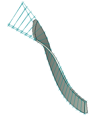
Fig 1.Non-ruled cutback edge
A common problem is that the ruled surface definition is “lost” during the design process. While the blade designer may intend to generate a two-section ruled definition, the final result may be a multi-section definition. This can happen if the choice of lead/trail edge construction requires trimming the ruled sides of the blade. The ruled surface is reparameterized between the lead and trail edges, resulting in a new non-ruled multi-section surface that is equivalent in shape. While this new data set may be useful for some purposes, the original ruled definition should also be exported for manufacturing, even if it extends beyond the edges.
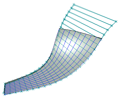
Fig 2. Multisection definition of trimmed ruled surface
Another issue arises when the ruled definition transitions unsmoothly to the lead/trail edge construction. This may be an attempt to force the ruled definition to suddenly conform to the edge construction. Typically this happens with rounded swept leading edges or blunt trailing edges. The resulting ruled surface will be unsmooth in that transition area. Since the flank-milling tool approximately follows the orientation of the rulings, unsteady cutting and a poor machined part will result. It is preferable to let the ruled definition continue smoothly past the swept edge, even if it means for example that the blade definition extends beyond the outer diameter of the part. Alternatively, the blade design system should have appropriate smoothing settings to improve the data.
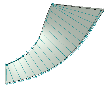
Fig3. Unsmooth transition at edges
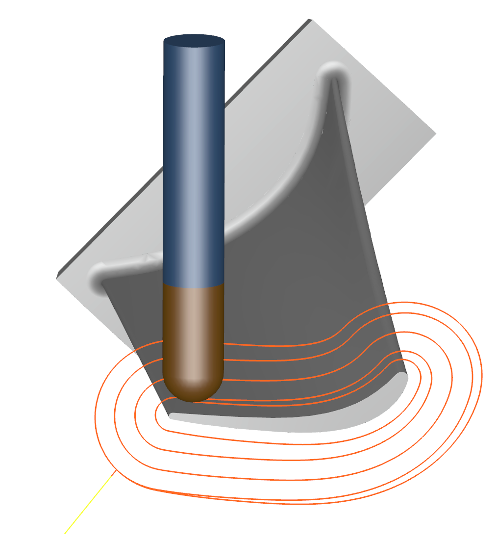
The ruled surface usually has some “twist” angle between the shroud and the hub. This is discussed in my previous blog, and should be considered during the design process. Flank-milling a twisted ruled surface in one pass with a conical/cylindrical tool results in geometric deviation that cannot be avoided. With extreme twists the deviation can go beyond the acceptable part tolerance. Our MAX-PAC™ CAM system minimizes this deviation and quantifies the results.
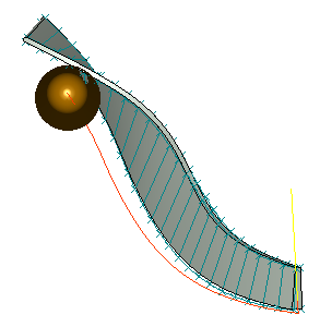
Fig 4. Flank milling of twisted ruled surface
The trailing edge region of a compressor blade can also be problematic for flank-milling. If the surface rulings become nearly vertical, then the tool orientation will approach the singularity (again described in my earlier blog) that gives unstable rotary motion. MAX-PAC has measures to handle this, but there may be cases that cannot be flank-milled with acceptable machine motion and part accuracy. Usually the situation can be remedied with a small adjustment to the geometry. The blade rulings can often be generously reoriented without a significant change in the blade shape.
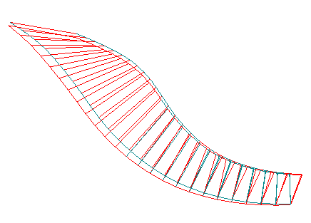
Fig 5. Adjustment of rulings at trailing edge
There are some important considerations when the ruled data is brought into a CAD system for detailed modeling. Usually the ruled surface is represented by two streams of XYZ points. The distribution of the points along these streamlines is important, and they might not be evenly spaced. The point spacing should be used for the parameterization of splines through the points, as well as surfaces created from those splines. CAD systems usually offer several options to loft a surface between curves, and the proper method should be selected to produce a ruled surface that reflects the original point distribution.
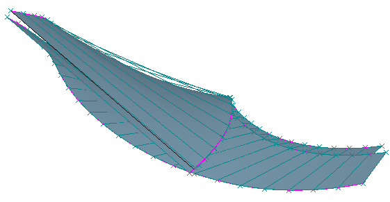
Fig 6. Visible deviation of rulings from improperly lofted surface
To avoid these pitfalls, it’s best to make a CAM review part of the blade design process.
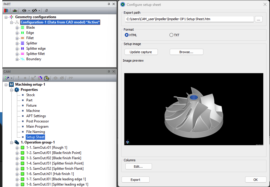
Here at Concepts NREC, we offer our customers a seamless link between our 3D blade design system, AxCent®, and our MAX-PAC CAM system. This means a new blade design can be quickly tested, with an example flank-milling path, to ensure that a high-quality part will be produced.