Turbine inlet temperature is one of the most critical parameters in the Brayton cycle of gas turbine engines. One way to increase the cycle efficiency is to increase the turbine inlet temperature, as illustrated in Figure 1. Here, a typical Brayton cycle T-S diagram chart visualizes the impact of higher turbine inlet temperatures on higher efficiency. Indeed, the area between the solid curves through points 0-3-4-8 represents the useful power generated by the turbine. The cycle efficiency can be calculated by dividing this area by the total area below curve 3-4, being the heat input. The dash lines convey the cycle with increased turbine inlet temperature, and the new cycle efficiency is the area in 0-3’-4’-8 curves divided by the area below curve 3’-4’. It is easy to see how a higher turbine inlet temperature increases cycle efficiency. Because of pursuing higher efficiency in modern gas turbine engine design, turbine inlet temperature has been pushed to a level that most material cannot withstand without effective cooling. Figure 2 shows the increasing trend of turbine inlet temperature since the 1940’s. Since the 1970’s, the turbine inlet temperature has been above material capability through the introduction of turbine cooling techniques.
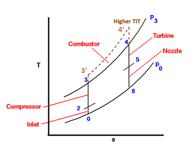
Figure 1. Brayton cycle in a T-S diagram. (Nancy Hall, 2015, “Ideal Brayton Cycle”, NASA Glenn Research Center. From https://www.grc.nasa.gov/www/k-12/airplane/brayton.html)
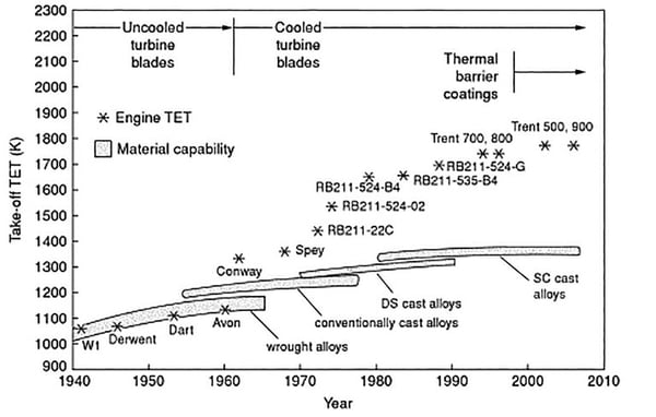
Figure 2. Turbine Inlet temperature development history. (https://www.mentor.com/products/mechanical/engineering-edge/volume3/issue2/gtre-heat-out)
Sophisticated techniques had been implemented to provide the best possible thermal protection or cooling coverage while using the smallest amount of cooling air, leading to improved system performance. As a highly effective cooling technique, film cooling became prevalent in turbine cooling. The mechanism of film cooling is to inject cooling flow through some holes embedded in the material surface, and generate a thin, cool, insulating layer of fluid over the surface to protect it from the high-temperature gas, illustrated in Figure 3.
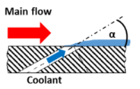
Figure 3. Illustration of film cooling conception. (https://tal.engineering.osu.edu/research/reverse-film-cooling)
Since the flow field in the turbine is highly 3-dimensional, and the temperature distribution is nonuniform, some locations are more vulnerable to thermal damage than others. Therefore, in modern gas turbine design, specific cooling performance is demanded at specific locations. To achieve optimum cooling performance, different cooling hole arrangements have been studied in the turbine passage, such as shower head at the leading edge, or film cooling on the pressure side and suction side surfaces, as well as the blade tip injection as shown in Figure 4.
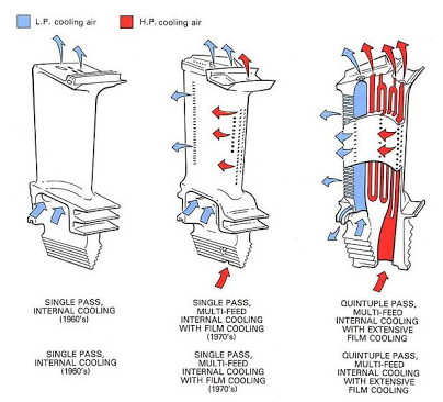
Figure 4. Multiple scheme of film cooling in gas turbine. (http://aeromodelbasic.blogspot.com/2012/01/bearing-chamber-cooling-development-of.html)
Computing temperature distributions on an actively cooled turbine blade is an enormously expensive undertaking using standard CFD and FEA analysis methods. Solutions like this require a coupled or “conjugate” heat transfer solution between the solid and fluid domains. Since the flow the near the cooling holes tends to be unsteady and very turbulent, advanced unsteady methods such Large Eddy Simulation are usually required which add to the cost.
Software, like the Cooled Turbine Airfoil Agile Design System (CTAADS) program, developed by Concepts NREC, provides a systematic and rapid 3D modeling approach to cooling-system design for cooled axial turbine vanes and blades. CTAADS includes many special features that can significantly reduce the total time and cost to generate airfoil cooling-passage geometry and perform a complete 3D thermal analysis.


