Why Meanline Scripting is Becoming Essential for Turbomachinery Design
Manual meanline design can sometimes feel less like design and more like managing a chain of tiny decisions.


The majority of the design effort in turbomachinery is spent focusing on the primary flow path. It is the primary driver of machine performance and performs the energy transfer the machine was designed for. However, secondary flow paths or leakage paths are essential to machine design and have large effects on both the performance and operation of the machine.
Secondary flows interact with the broader machine and influence overall machine performance. They are required for mechanical design and are often used for cooling or thrust management. Accounting for these effects has historically been an afterthought for many turbomachinery designers. This means that the primary flow path layout is often settled by the time leakage flows are accounted for.
Introducing secondary flow paths into the design process sooner can ensure that they are laid out intentionally and that the impact on performance is accounted for upfront.
Secondary flow paths take many forms. Some paths occur as an unavoidable consequence of the machine’s operation while others are deliberately introduced to perform a specific function. Balancing thrust loads, controlling pressures across different internal surfaces, or active blade cooling are all possible examples here.
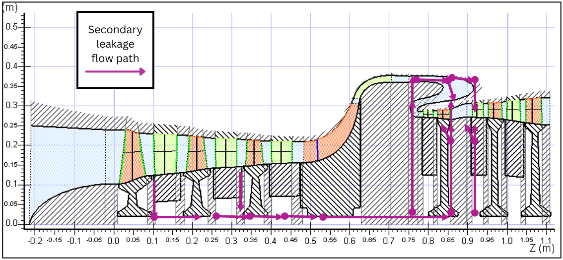 Secondary flow path illustrated in purple
Although these flows represent only a small portion of the total flow through a machine, their effects are not necessarily confined to the secondary flow path itself. Fluid that leaves or reenters the primary flow path will change the mass flow, pressure, temperature, and energy balance at different points in the machine.
Understanding where the fluid comes from, where it goes, and how it changes along the way helps engineers more accurately evaluate the impact those flows have on the overall system.
Early-stage turbomachinery design depends on simplified models that allow engineers to evaluate design options quickly and efficiently. As a design progresses, those models become more detailed, moving from cycle analysis to preliminary or meanline, into 3D geometry, CFD, and optimization.
The challenge is maintaining a consistent representation of secondary flow as fidelity increases. A secondary flow considered during preliminary design may require additional calculations or modeling when the 3D geometry is created, and that information needs to remain consistent as the design moves into CFD and other forms of analysis.
When these stages are disconnected, engineers may need to manually transfer information, recreate secondary flow paths, or update the same assumptions in multiple places. This makes accounting for secondary flows early less practical if the work performed at one stage cannot easily be carried into the next.
As a result, many engineers choose basic assumptions about the effects of secondary flows until much later in their design process. If these assumptions prove false, it can be difficult and costly to update previous design choices. Earlier consideration allows for better decision making at each step in the process.
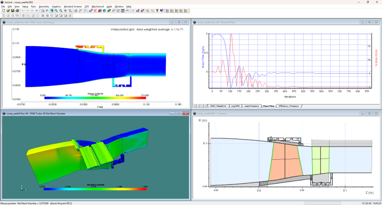
Accounting for secondary flows earlier doesn’t mean performing high-fidelity analysis from the start. Instead, realistic modeling of secondary flows at the meanline level translates to stronger 3D geometry and allows for refinement as the design comes together.
With an integrated workflow, a secondary flow introduced during meanline design will be carried into subsequent design stages. As the design moves into 3D geometry and CFD, engineers are enabled to add additional detail and refine their understanding of the flow without starting over. Higher-fidelity results can then be used to update assumptions and better understand the impact on overall machine performance.
When the information created at one stage can support the work that follows, engineers can consider these effects sooner without duplicating the same effort later. Each level of analysis adds to the understanding developed in the previous stage, creating greater continuity from preliminary design through detailed analysis.

This type of connected workflow is now possible in the Agile Engineering Design System® thanks to new capabilities for secondary flow design and analysis, developed as part of a recently completed SBIR project through the Department of the Air Force AFWERX program.
Secondary flows may sit outside the primary flow path, but their effects are connected to the performance of the machine as a whole. Accounting for them earlier gives engineers more opportunity to understand those effects and incorporate what they learn as the design develops. Our engineers work with these challenges every day, and the capabilities added through this work reflect that experience: a more connected workflow and a more complete accounting of the machine's performance.
See this approach in practice during our webinar, Cooling and Secondary Leakage Path Design: Enhancing Accuracy Through an Integrated Workflow. We demonstrate how secondary flow paths can be incorporated into the design and carried from cycle analysis through meanline, 3D geometry, and CFD.

Tags: CAE Software
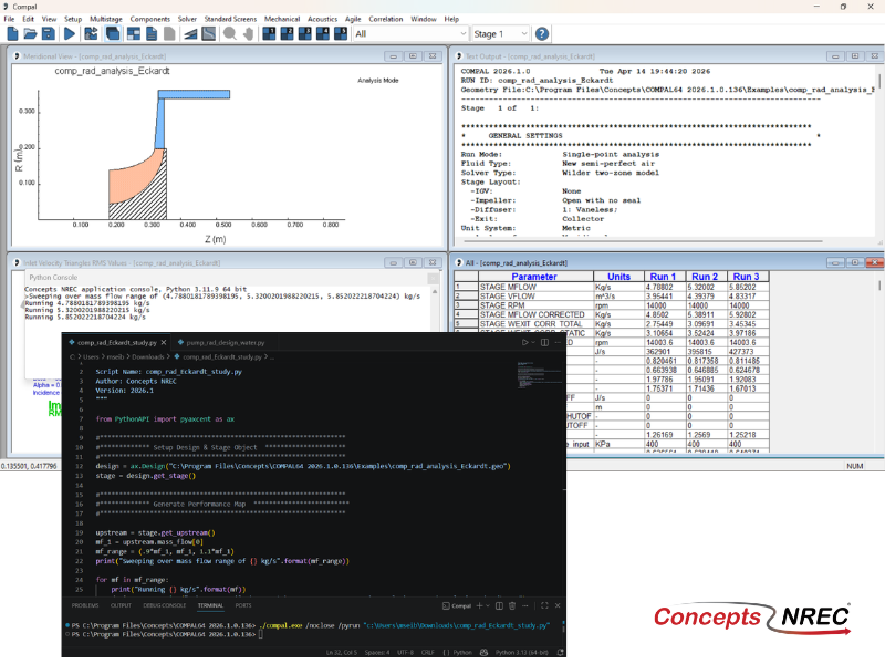
Manual meanline design can sometimes feel less like design and more like managing a chain of tiny decisions.
For most turbomachinery engineers, optimization isn’t a new idea. It’s a critical part of their workflow that can’t be overlooked. But sometimes that crucial step isn’t easy to get to.