There are two dominant manufacturing methods used to produce turbomachinery parts – Casting and 5-axis machining. This blog will explore some of the applications and restrictions of these two methods.
Casting
Casting comes with some unique restrictions, primarily, the ability to pull the mold from the product. There are various techniques to accomplish this, each with their own limits and costs. Lost wax methods of casting provide the most flexibility. Other methods require complex three‐dimensional calculations to determine if proper clearances are present to free the casting, as the molding components are pulled and twisted away. A primary drawback to casting is that it generally does not achieve the same quality (in terms of tolerance and surface finish) as milled parts. The accuracy of the finished product is rather difficult to predict and control due to expansion and motion of the thin-walled blade structures. This complicates the task of balancing as well. The initial setup costs for casting make it practical only for high volume production.
5-Axis Machining
Computer-controlled 5-axis machining plays a huge role in turbomachinery component manufacturing. This is particularly true for compressor impellers, but 5-axis machining is gaining in popularity even in areas previously dominated by casting, such as pump and turbine rotors. The advent of 5-axis machining in the 1970s and 1980s sparked a revolution in manufacturing which enabled unprecedented flexibility and quality of the finished part. Three general paradigms are used today for 5-axis machining of turbomachinery: flank milling, point milling, and integral shroud milling. A fourth method, flank milling, is also used but predominantly on axial blades.
Flank Milling
Flank milling uses the side of a cutting tool (usually straight sided) to form the blade surface in one pass. These blade surfaces are defined by a series of straight lines that curve in three-dimensional space. These straight lines are roughly perpendicular to the joining hub and shroud surfaces and are sometimes called quasi‐orthogonal lines. Computer‐Aided Manufacturing (CAM) methods are used to guide the cutting tool in a 5‐axis milling machine, with the tool oriented roughly according to the straight line elements.
Point Milling
Sometimes the blade surface cannot be represented with true quasi‐orthogonal lines and more flexible parameterization is needed which allows twist in the blade. This requires a process which is generally slower and more expensive called point milling. With point milling, a ball-end tool contacts only at one point and makes many passes to form the blade. Variations involve barrel-shaped tools and milling in multiple strips. The goal is to reduce the number of passes of the tool to save time, while still maintaining adequate surface finish. The additional geometric control that point milling provides is generally considered essential for most axial designs.
In contrast, radial compressors rarely benefit enough from non-ruled element layouts to justify the increased cost of point milling. Radial turbines are even less sensitive aerodynamically to the constraints of flank milling. Radial turbines are still typically cast, but 5‐axis machining is increasing in favor due to cost-effective cutting methods, more accurate geometry results, and the superior surface finish resulting from milling. The same is true in other areas that have traditionally used casting.
Integral Shroud Milling
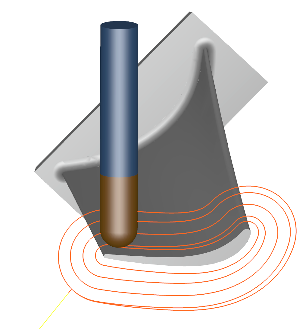
The third and most difficult method of rotor machining, is an integral shroud layout, machined from a single piece of metal. The technique requires the cutting tools to enter the passage from the inlet and exit planes. This usually forms two cavities that meet in the center of the passage. The resulting part produces superior structural characteristics, as well as some aerodynamic advantages. The aerodynamic advantage comes, primarily, from eliminating the sheer force on the fluid incurred when the stationary shroud moves, relative to the rotating passage. Special cutting tools, referred to as lollipop cutters, are used to maximize access to the interior of the passage that is difficult to reach. Some designs are simply not feasible with integral shroud machining, since the center of the passage might, simply, not be reachable. This feasibility is determined from a complicated combination of geometric parameters, including passage wrap, lean, and height. Practical limits of the cutting tool also come into play when excessive length-to-diameter ratio leads to too much tool deflection.
End Milling
Another, less frequently used method, is end milling. End milling uses the flat end of a cylindrical cutting tool or a slightly modified version with a rounded edge called a bull-nose. End milling requires a lot of access to the passage to avoid collisions, so its most frequently used in single-blade machining for axial designs.

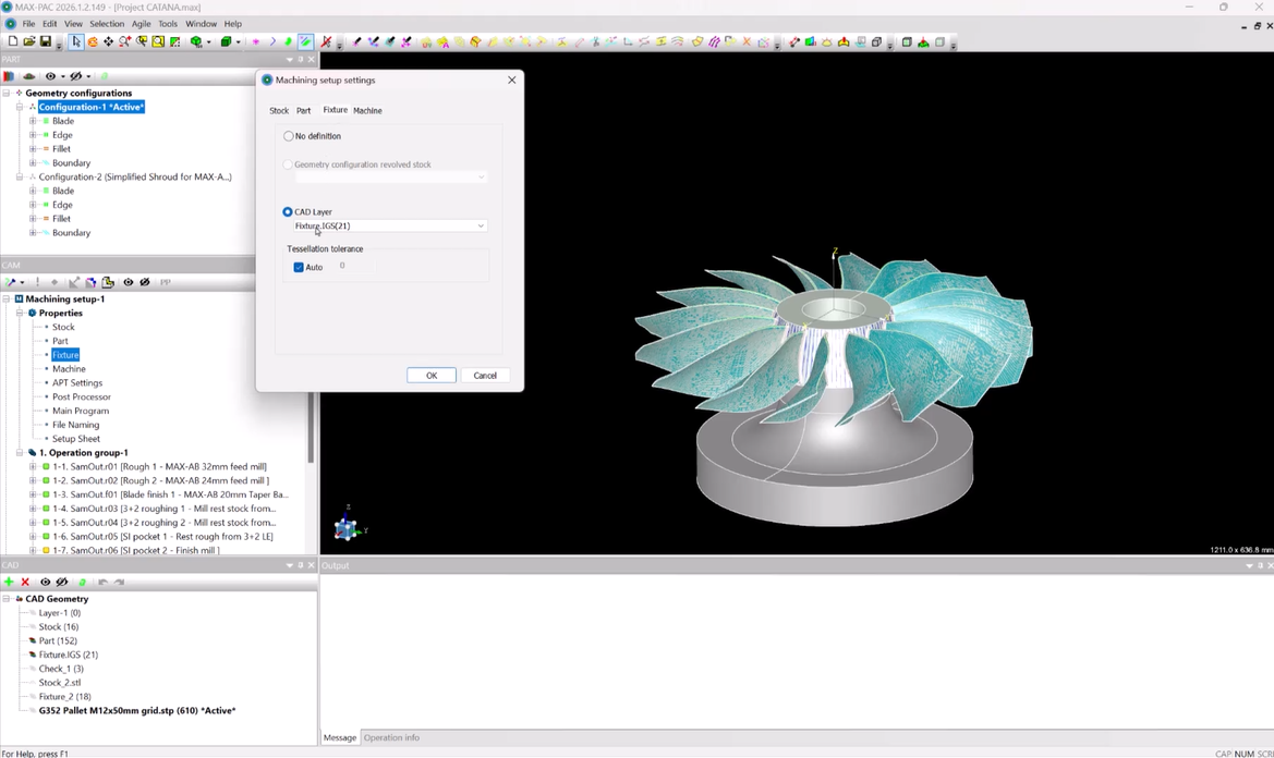
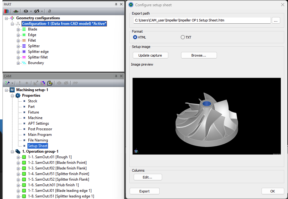
It is critical to choose the right Computer-Aided Manufacturing (CAM) software to create the optimal cutter-path solutions for your turbomachinery components. MAX-PAC™ has long been recognized as the best software for 5-axis milling of turbomachinery impellers, blisks, and rotors. MAX-PAC is used worldwide by turbomachinery manufacturers, job shops, and 5-axis machine-tool manufacturers who are passionate about producing the highest-quality parts.
Learn more about MAX-PAC™