Why Meanline Scripting is Becoming Essential for Turbomachinery Design
Manual meanline design can sometimes feel less like design and more like managing a chain of tiny decisions.


The compressor is generally one of the most sensitive components of an sCO2 cycle. This makes it a challenge to design a robust compressor while keeping the thermodynamic cycle close to optimal.
The typical compression process in an sCO2 cycle is shown in Fig 1. The compressor inlet point position on a TS diagram depends on the low temperature heat source. And the compressor inlet pressure is often selected for the max power criterium. That requirement pushes the compressor inlet pressure to the supercritical liquid region, not necessarily providing a margin to the saturation dome. Consequently, inlet conditions for optimal cycle efficiency can lead to the risk of two-phase flow appearance in certain regions of the compressor flow path. This situation can be prevented by tuning either the inlet pressure or the inlet temperature. Yet there is a trade-off between cycle efficiency and these compressor inlet conditions.
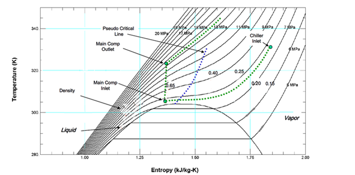
Figure 1. Temperature Entropy diagram for CO2 near the critical point
There is no need to list for the turbomachinery community the potential risks of the two-phase flow condition inside the compressor. Even if nucleation does not damage the impeller blades, it can have a detrimental effect on the rotor bearing system, which can be substantial for high-speed magnetic bearings.
Figure 2 shows an impeller inlet point in the danger zone of the saturation dome without a reasonable margin. A 3D CFD model of a preliminary impeller design revealed a two-phase zone at the impeller LE (Figure 3).
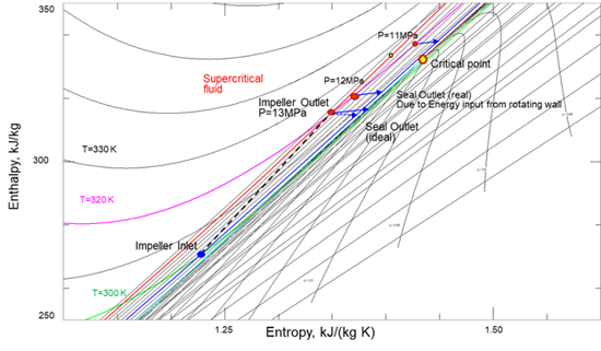
Figure 2. Process in compressor shroud seal on sCO2 h-S diagram
Concepts NREC uses the FINE/Turbo CFD code in several phases of the design process, starting from an express CFD analysis of preliminary flow path designs to a risk matrix for the high fidelity CFD analysis of final geometry for turbomachine map generation. Particularly for the case in Figure 3, the design of LE geometry was not sufficient to guarantee robust compressor performance.
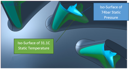
Figure 3. Pressure/Temperature Iso-Surfaces
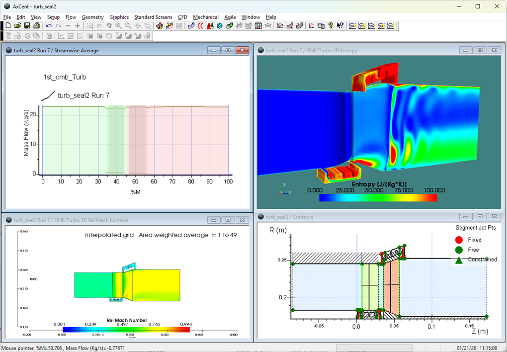
In a shrouded impeller design with stepped seals, the aero designer must make a risk assessment of the flow in sCO2 compressor seals. Pressures in seal regions can drop to values that do not leave margin above the saturation dome. These complementary simulation results show that in this case the original recommendation for the choice of the inlet temperature and pressure was not sufficient to assure a margin to the saturation dome throughout the flowfield.
There is still no general quantitative guidance that can be recommended since the relevance would be limited to the specific compressor geometry, and other factors must also be taken into account.
To conclude, the prevention of two-phase flow in an sCO2 compressor requires coping with the effect of flow not only in the primary flow path, but also in the secondary flow paths. Revisiting the compressor inlet conditions is required in an aero design process for any sCO2 turbo system. Risks for compressor design on the “cold” side of a turbogenerator are still high, especially when considering the rapid density changes possible, unknown startup transients, etc.
We welcome your questions and comments here or contact us at info@conceptsnrec.com for further dialogue.
Tags: CAE Software, Engineering, Supercritical CO2, SCO2

Manual meanline design can sometimes feel less like design and more like managing a chain of tiny decisions.

For most turbomachinery engineers, optimization isn’t a new idea. It’s a critical part of their workflow that can’t be overlooked. But sometimes that crucial step isn’t easy to get to.
It’s no secret that turbomachinery design has been one of the most demanding CAE environments, thanks to tight tolerances, complex physics, and long design cycles. That hasn’t changed in 2026, but...