Why Meanline Scripting is Becoming Essential for Turbomachinery Design
Manual meanline design can sometimes feel less like design and more like managing a chain of tiny decisions.


Many gas turbines with radial compressors utilize a radial-to-axial inlet duct upstream of the first compressor stage. Aside from the fact that flow in the duct generates aerodynamic losses, the flow profiles at the duct exit, delivered to the inlet of the first impeller, also affects the performance of the compressor.
To demonstrate how duct geometry may affect duct and compressor inlet conditions, let’s consider a simplified test case in which the duct can be optimized for reduced duct loss in a domain that also includes a fixed geometry impeller.
Optimization problem formulation:
Consider a radial-to-axial flow duct with fixed predesigned 3D impeller geometry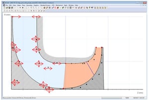
Allow the duct hub and shroud contours to be variable, while inlet radius and exit dimensions and overall axial extent of the duct are fixed.
Use 3D CFD to analyze the flow in the domain
Optimization targets are set to maximize the (P0exit/P0inlet) ratio in the duct (i.e. minimize loss) and minimize the relative Mach number (mass-flow averaged value) at the impeller tip, which gives a trade-off problem with a Pareto front of best solutions, the result of the optimization
The optimization problem was executed using TurboOpt ll™, Axcent® and a 3rd-party optimizer (IOSO PM) to run parallel multi-objective optimization using a cluster of computers. An initial duct geometry is set using a simplistic design, based on a reasonable straight line + arc definition and then converted to Bezier for better flexibility during optimization. The initial geometry reported a relative Mach number at the impeller inlet tip of ~ 1.25, with the duct (P0exit/P0inlet) ~ 0.993, for reference.
The resulting Pareto front and geometry layouts with overlay, compared to the initial duct geometry, are shown in the Figure 1 below:
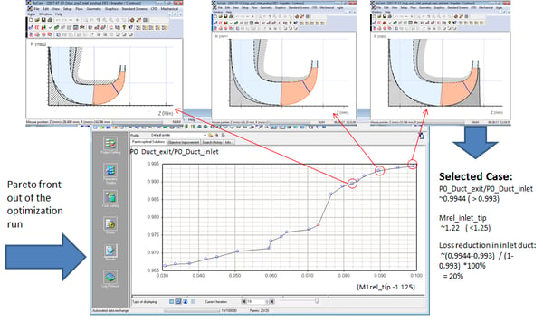
Figure 1. Results of the optimization for the radial-axial duct shows significant performance improvement
The results above show the apparent trade-off, higher (P0exit/P0inlet) in the duct (lower duct loss), correlates well with an increase in the relative inlet Mach number at the tip. The duct geometries with reduced losses (correspondent to the red circles in the Pareto front in Figure 1) are quite different from the simplistic starting duct geometry. The duct geometries show complex streamwise variations in duct contours, slopes and curvatures, as shown in Figure 2. In particular, peak shroud curvature is shown in these results to be a strong factor for the relative inlet Mach number at the impeller tip.
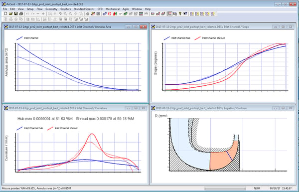
Figure 2. Overlay of annulus area, slopes and curvatures for lowest loss and original duct geometries
The optimized duct geometry has a ~ 20% loss reduction, and a lower relative inlet Mach number at the impeller tip (1.22 vs 1.25), versus initial duct design. This improvement is without reduction of the available space under the duct hub, which is usually an important location for the shaft bearing. This resulting design is beneficial for the compressor and overall engine performance.
Impellers are often designed with certain parametrization rules which can limit the range of 3D shapes possible. Ruled blade surfaces, for example, are used in most of the 3D impellers found in radial compressors. This can restrict the range of incidence angle the designer can work with, and the result may or may not be ideal for what is delivered by the inlet duct. The best approach, therefore, is to optimize the inlet and impeller together to deliver the best possible performance for a given parameterization requirement.

Manual meanline design can sometimes feel less like design and more like managing a chain of tiny decisions.

For most turbomachinery engineers, optimization isn’t a new idea. It’s a critical part of their workflow that can’t be overlooked. But sometimes that crucial step isn’t easy to get to.
It’s no secret that turbomachinery design has been one of the most demanding CAE environments, thanks to tight tolerances, complex physics, and long design cycles. That hasn’t changed in 2026, but...