Why Meanline Scripting is Becoming Essential for Turbomachinery Design
Manual meanline design can sometimes feel less like design and more like managing a chain of tiny decisions.


Most turbomachines need to operate across a range of fluid flow rates and speeds. This is obvious in transportation applications where gas turbine engines and turbochargers need to operate at all of the speeds, altitudes and temperatures that the vehicles they power will encounter. In industrial and refrigeration applications, turbomachines need to have a wide operating range to make them appealing to end users who want efficiency under many operating conditions.
In the traditional turbomachinery design process, the design engineer starts with a single design point. The design point will be a carefully selected speed and flow where the machine will operate at its peak efficiency. Then the machine is designed around this design point and analyzed under off-design conditions to determine its range. The key point is the difference between “design” and “analysis”. Design implies that the machine geometry is fluid and can be adjusted. Analysis implies a fixed geometry which is analyzed at various operating conditions.
When we are designing new products for clients or training new users on our Agile Engineering Design System®, they rarely have a single design point as the product specification. Instead, they want a performance map which involves specifications for performance at a several different speeds and flow rates, a much more difficult task.
Knowing this, we have programmed our software with a number of capabilities to enable true design (as opposed to analysis) at multiple operating points. Here are a few key items worth highlighting:
The first is optimization algorithms. The compressor map below shows a starting geometry (base case) and then performance specifications at two different operating points.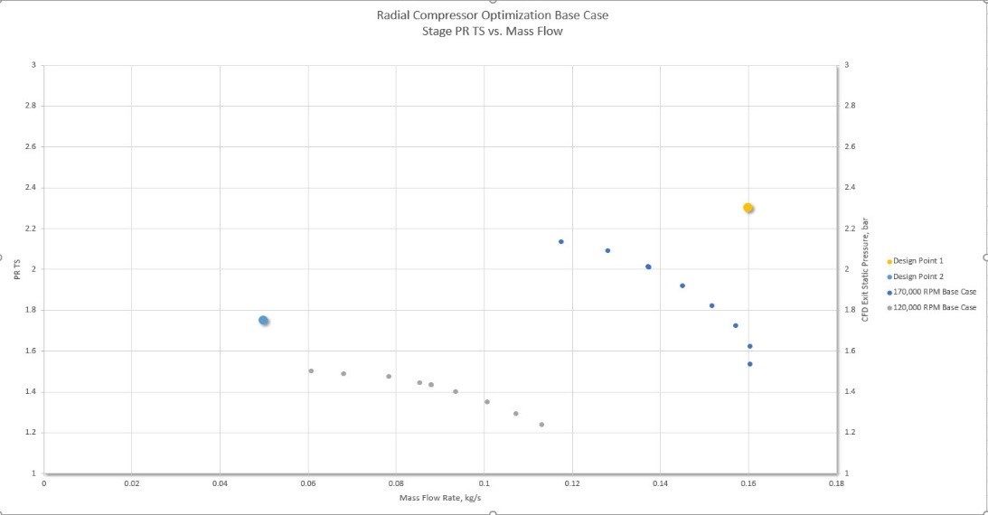
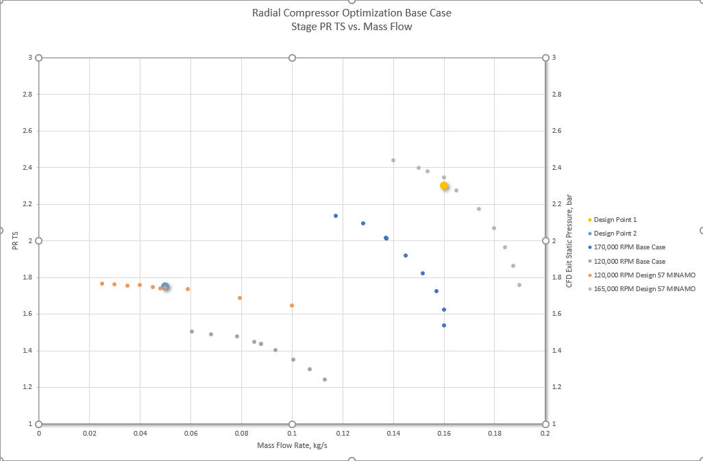
We set up the problem as Multidisciplinary Optimization (MDO) problem, where there are 4 targets: pressure ratio and efficiency at the low-flow condition and pressure ratio and efficiency at the high-flow condition. We then use an optimizer to drive the codes to achieve all 4 of these results. The map below shows the optimized design and the figures below that show the modifications to flow path contours and blade angles the optimizer made using the AxCent® software to drive the geometry and the FINE/Turbo CFD code to calculate performance.
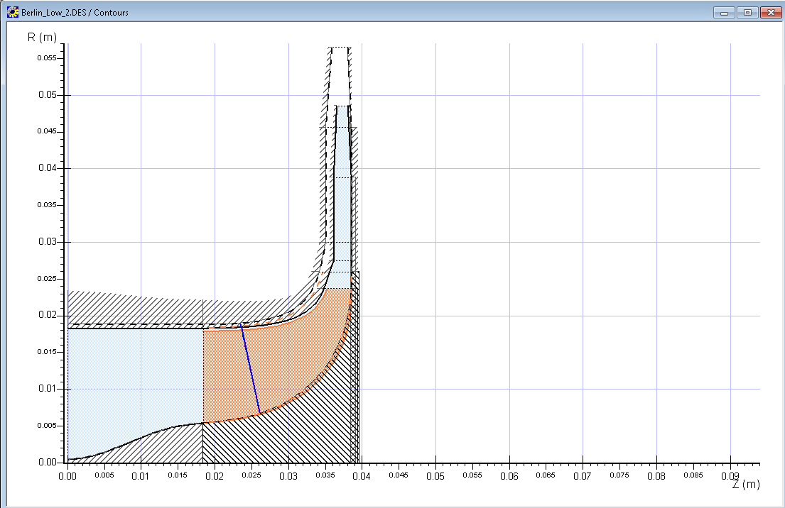
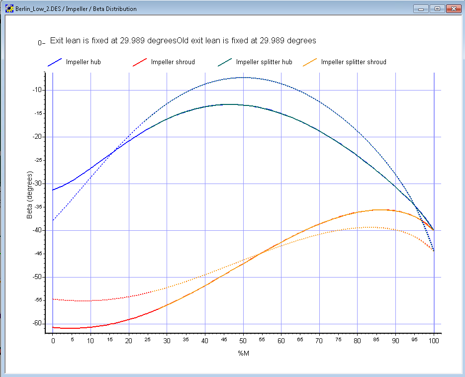
Solid lines = Base case
Dashed lines = Optimized design
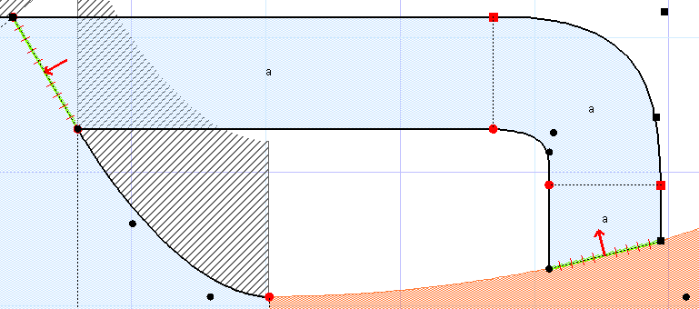
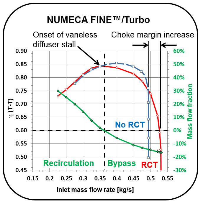
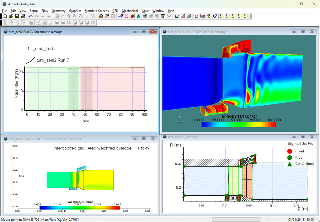
The second capability dedicated to range extension is the ability to design casing treatments. A casing treatment is a bypass path that can allow excess flow to bypass the choke point extending range at the high end and to recirculate back to the inlet extending range at the low end. The figures below show a casing treatment geometry designed using AxCent, and the subsequent flow modeling done using FINE/Turbo at various operating conditions across the map and the resulting range extension.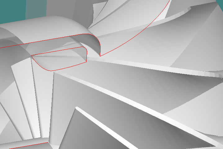
All of these features are designed to meet the real world need of OEMS who are looking to design products that meet performance specifications at a variety of speeds and flows, rather than one design point.
Tags: CAE Software

Manual meanline design can sometimes feel less like design and more like managing a chain of tiny decisions.

For most turbomachinery engineers, optimization isn’t a new idea. It’s a critical part of their workflow that can’t be overlooked. But sometimes that crucial step isn’t easy to get to.
It’s no secret that turbomachinery design has been one of the most demanding CAE environments, thanks to tight tolerances, complex physics, and long design cycles. That hasn’t changed in 2026, but...