Why Meanline Scripting is Becoming Essential for Turbomachinery Design
Manual meanline design can sometimes feel less like design and more like managing a chain of tiny decisions.


PCs and workstations are getting faster every year, following Moore's Law. With all this power and speed, the “virtual prototyping” of turbomachinery, using CFD simulations and optimization algorithms is getting more and more common. In this context, one may question if meanline design still makes sense. Let's explore the implications of this question. To do this, we have to go back to basics.
What is meanline or 1D design/analysis? Basically, in this approach, the machine elements (impeller, diffuser, return channels, etc.) are considered control volumes and, therefore, only inlet and exit properties are considered. When analyzing a machine, the primary geometry parameters are typically input, such as radii, angles, blade heights, etc. The model then calculates its performance for one streamline (the Root Mean Square Streamline - “ah, that’s where the name comes from”). Meanline codes can also operate in design mode, where these geometry parameters are calculated to meet certain flow targets such as pressure rise and flow rate.
Using meanline, the designer can quickly evaluate the effect of key elements, such as backsweep angle, and load distribution in different stages. They can also impose geometry constraints, which are necessary when designing a machine that will use existing casing or shafts. Even with these constraints, meanline still enables the designer to keep exploring the remaining geometrical options. It is also possible to evaluate the geometry's performance for different flow rates, rotational speeds, and more. This capability can generate a whole performance map for a theoretical machine that, 20 minutes prior, all you had was an idea about pressure ratio, rotational speed and flow rate. Cool, huh?
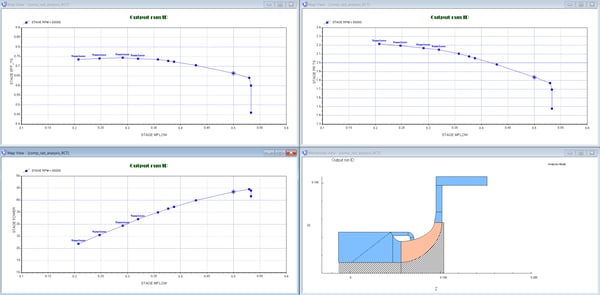
A Performance Map for one Speed line made in Compal for a Turbocharger’s Centrifugal Compressor with Recirculating Casing Treatment
This means that meanline is a very powerful tool that, combined with today's computational capacity, can quickly explore trade-offs and provide data to make good preliminary design decisions. These include how many stages, what kind of diffuser, etc. Meanline also gives instant feedback on component performance and tells the user where to focus their efforts for improvement. Just keep in mind that meanline models are based on a combination of physics-based rules and empirical data, so the user needs to be careful if these limits are exceeded.
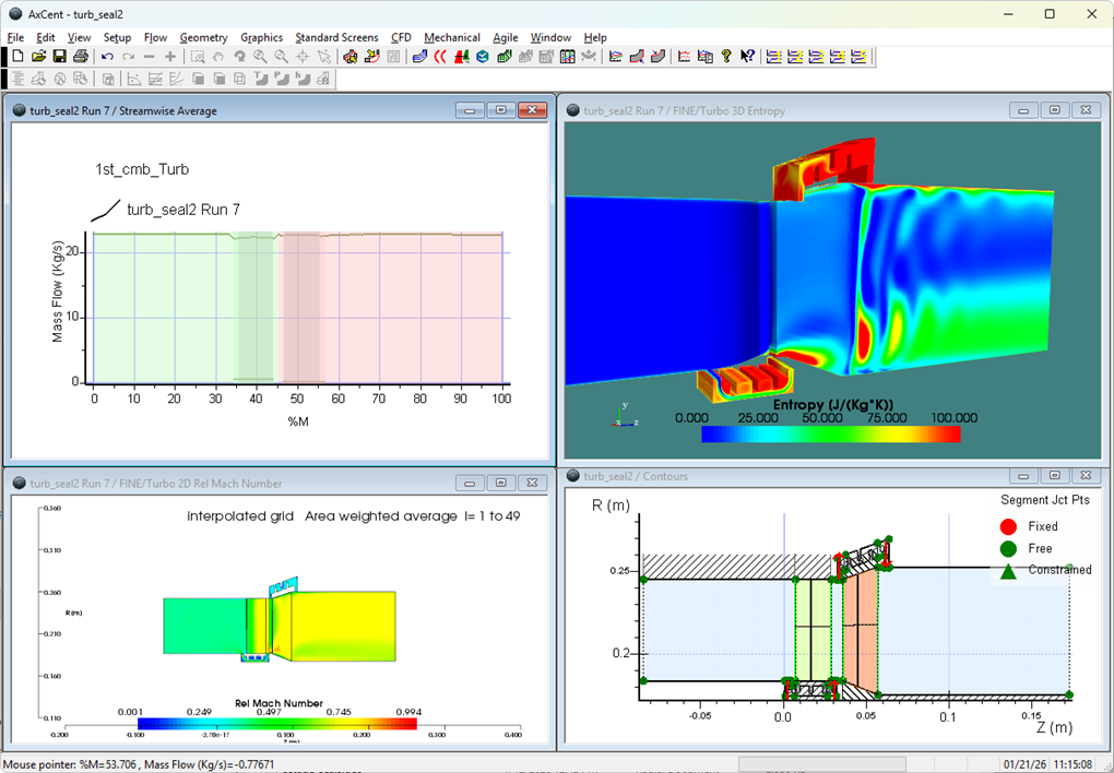
The main outcome is the overall size, shape, and flow states of the machine that is then used in a detailed design tool, like AxCent®, where the full 3D geometry will be defined, including meridional contours, angle distribution, and thickness. Once the preliminary design and 3D geometry are set, then CFD runs and optimization techniques can be applied. Optimization tweaks the machine parameters to find the best design for the given geometry.
Some engineers are so confident in the accuracy and fidelity of today's CFD results, combined with robust optimizers, that they question the need for meanline models at all. Do they have a point? Can digital tools, or even robots, replace an engineer? While CFD has indeed enabled engineers to investigate details never even imagined 30 years ago, and optimizers have found some really nontrivial designs, it is not a perfect process. These are still Computer-Aided Engineering software tools, and not engineers. A CFD simulation can be missing some important physics, say, due to mesh quality or turbulence model, even though convergence looks great. Even with good and stable CFD simulation, it can be very difficult for an optimizer to improve the overall design much if the baseline shape is too far away from the targets. Getting this proper baseline shape is what meanline is all about.
Above all, there is an important set of decisions which need to be made early in the project before any mesh is even created. Here is an example: should Inlet Guide Vanes be used to increase the machine range of operation? This has ramifications for, not only the vanes themselves, but the electric motors to drive it, wiring, sensors and the control system. Design engineers need to weigh the range improvements, with the additional manufacturing costs, and impact to project timing. This becomes easy by using COMPAL, or another meanline code for centrifugal compressors. The designer can evaluate the impact of adding IGVs and check different scenarios and the possible range operation gains.
Mark Anderson, Concepts NREC's CTO, points out that “Effective engineering is not just about having the most accurate prediction possible. It’s about getting the best design possible in a finite time and budget. Using meanline lets you explore many, many more possibilities and narrows in faster on the best design space.”
Think of it as another example of the 80/20 rule. Eighty percent of the decisions are defined and done with twenty percent of the work. That’s when it makes sense to empower talented engineers with helpful tools to evaluate scenarios, trade-offs, etc. Then you can employ the resource intensive optimization to run thousands of iterations to reach new levels of performance.
So, my conclusion is yes, meanline design tools are still very helpful. They are complementary to higher level tools, such as CFDs and optimization. It is even possible to perform meanline optimization, read about it in my colleague, Oleg Dubitsky's blog: Optimization of Cycle Parameters, Fuel Consumption, and Weight of a Turboshaft Engine Using 1D Design Tools.
Special thanks to the following people for helping me with this blog:
Mark Anderson, CTO at Concepts NREC
Dr. Magnus Genrup, Professor, Department Head at Lund University
Dr. Dimitri Deserranno, Head of Aerodynamics at Concepts NREC
Tags: CAE Software, Engineering

Manual meanline design can sometimes feel less like design and more like managing a chain of tiny decisions.

For most turbomachinery engineers, optimization isn’t a new idea. It’s a critical part of their workflow that can’t be overlooked. But sometimes that crucial step isn’t easy to get to.
It’s no secret that turbomachinery design has been one of the most demanding CAE environments, thanks to tight tolerances, complex physics, and long design cycles. That hasn’t changed in 2026, but...