COMPAL

Radial Compressor Design Software

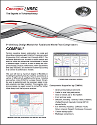
A meanline approach is used to rapidly design and analyze radial and mixed-flow compressors for single or for multiple stages. COMPAL® is used to design the compressor stage, analyze performance, refine parameters with data reduction, and model the machine according to a number of performance models. COMPAL's unique Design Wizard leads the user through all the necessary steps for design, analysis, and data reduction. The meanline compressor design can easily be sent to the AxCent® program for further blade design and fluid dynamic analysis.

Components Supported by COMPAL:

  • Upstream/downstream elements
  • Radial or axial inlet guide vanes
  • Open or closed impellers
  • 2D or 3D impellers
  • Front and rear seals
  • Diffuser types, including…
    • Arbitrary vaned
    • Vaneless
    • Wedge/channel
    • Cascade
    • Conical
    • 90/180 degree bends
  • Exit elements, including…
    • Collector
    • Volute
    • Return channel
    • Deswirl
    • Continuous crossover
    • Various leakage paths
    • Multistage compressors

Modeling

COMPAL supports two-elements-in-series (TEIS) rotor diffusion modeling through a two-zone loss modeling approach, disk friction, exit mixing, radial and axial stator diffusion/losses, volutes, inducer choke, stall, thrust, and other fundamental fluid dynamic aspects of compressor performance. Many alternative models are also available.

Integrated Performance Map Plotting

Review design performance, analysis, and test data with flexibly plotted performance maps, updated automatically with each geometric change.

Easy Editing

View the compressor stage in an active, true-scale meridional view. Edit the parameters by double clicking on the component in the meridional view. Also, edit parameters using a single text input/output file, a feature especially useful for optimization.

Tabular View of Results

View the results in a flexible, spreadsheet-like table, customizable through separate filters. Create any number of filters, select what to display, and customize the labels as well.

Axial View with Velocity Triangles

View blades and velocity triangles at the impeller inlet and exit in a window view. View inlet velocity triangles for the hub, tip, or RMS radius, and exit velocity triangles for the primary and secondary zones, and mixed-out state.

OLE Automation Support

Control COMPAL from an external program through industry-standard Object Linking and Embedding (OLE) automation. OLE automation supports full control of data entry, program execution, and result retrieval. External programs can be written in Visual Basic, C++, FORTRAN, or any other language that supports the Microsoft® OLE standard.

Multistage Capability

COMPAL supports multistage analysis and data reduction, and provides a variety of multistage performance maps.

A Real Fluid Program

COMPAL calculates Real Fluid properties using optional DB Robinson Real Fluid Properties, NIST, or ASME Steam routines. Users can also incorporate their own proprietary fluid properties.

Direct Integration with AxCent®

AxCent can start automatically from within COMPAL, with the initial geometry transferred automatically to AxCent. Changes in AxCent that affect the meanline analysis will cause the meanline analysis to be rerun and all performance maps to be regenerated.

partner-bg-img

Software Highlights - Aungier Model Calibration

Components Supported by COMPAL

  • Upstream/downstream elements
  • Radial or axial inlet guide vanes
  • Open or closed impellers
  • 2D or 3D impellers
  • Front and rear seals
  • Diffuser types, including…
    • Arbitrary vaned
    • Vaneless
    • Wedge/channel
    • Cascade
    • Conical
    • 90/180 degree bends
  • Exit elements, including…
    • Collector
    • Volute
    • Return channel
    • Deswirl
    • Continuous crossover
    • Various leakage paths
    • Multistage compressors

Modeling

COMPAL supports two-elements-in-series (TEIS) rotor diffusion modeling through a two-zone loss modeling approach, disk friction, exit mixing, radial and axial stator diffusion/losses, volutes, inducer choke, stall, thrust, and other fundamental fluid dynamic aspects of compressor performance. Many alternative models are also available.

Integrated Performance Map Plotting

Review design performance, analysis, and test data with flexibly plotted performance maps, updated automatically with each geometric change.

Easy Editing

View the compressor stage in an active, true-scale meridional view. Edit the parameters by double clicking on the component in the meridional view. Also, edit parameters using a single text input/output file, a feature especially useful for optimization.

Tabular View of Results

View the results in a flexible, spreadsheet-like table, customizable through separate filters. Create any number of filters, select what to display, and customize the labels as well.

Axial View with Velocity Triangles

View blades and velocity triangles at the impeller inlet and exit in a window view. View inlet velocity triangles for the hub, tip, or RMS radius, and exit velocity triangles for the primary and secondary zones, and mixed-out state.

OLE Automation Support

Control COMPAL from an external program through industry-standard Object Linking and Embedding (OLE) automation. OLE automation supports full control of data entry, program execution, and result retrieval. External programs can be written in Visual Basic, C++, FORTRAN, or any other language that supports the Microsoft® OLE standard.

Multistage Capability

COMPAL supports multistage analysis and data reduction, and provides a variety of multistage performance maps.

A Real Fluid Program

COMPAL calculates Real Fluid properties using optional DB Robinson Real Fluid Properties, NIST, or ASME Steam routines. Users can also incorporate their own proprietary fluid properties.

Direct Integration with AxCent®

AxCent can start automatically from within COMPAL, with the initial geometry transferred automatically to AxCent. Changes in AxCent that affect the meanline analysis will cause the meanline analysis to be rerun and all performance maps to be regenerated.

Product Support

COMPAL Brochure

Perform meanline design optimization for radial and mixed-flow compressors for single or multiple stages. COMPAL is used to design the compressor stage, analyze performance, refine parameters with data reduction, and model the machine according to a number of performance models.

COMPAL

Find Your Rep

Our Sales Offices are strategically located around the globe to service all your turbomachinery needs.

Upcoming Events

Tradeshows, Workshops, Webinars and more.

I came to the realization that we needed some objective insight.

We were working well with the OEM but even with our combined efforts, we were struggling to get a critical compressor to pass performance on their test stand. Although I'd never directly done business with Concepts NREC I was familiar with them and their capability so I chose to contact them when I came to the realization that we needed some objective insight. Concepts NREC fielded my cold call and immediately engaged their expertise in a complex problem that was also challenged by schedule constraints. They provided increased understanding of an already complex CFD which resulted in increased confidence that the proposed solution would succeed on the next test stand attempt (which it did!). We are pleased to have had the help of Concepts NREC and now have a well-performing compressor in our process.”

Bryan Barrington

Senior Advisor - Machinery Engineering

Related Blog Articles

The Gyroscopic Effect
CAE Software
The Gyroscopic Effect
by Thomas Gresham, Senior Mechanical Design Engineer
This post covers one of the fundamental issues that makes rotordynamics a unique subject: The Gyroscopic Effect. The gyroscopic effect can be observed in the behavior of spinning tops, fidget spinners, inertial navigation systems, and many types of turbomachinery. If you have ever tried to tilt an object while it is spinning, then you may have noticed this effect.
Continue Reading
Part 2: Hydrogen Turbomachinery Design
CAE Software
Part 2: Hydrogen Turbomachinery Design
by Mark R. Anderson, Chief Technical Officer, Concepts NREC
Hydrogen is attracting a lot of interest in different circles these days from: propulsion, to energy storage, to personal transportation. The most obvious benefit of hydrogen fuel is a total lack of carbon in the exhaust products. This is rare for a fuel that’s a fairly high energy substance to begin with. More specifically, its high energy in terms of energy per unit of weight but somewhat less so in terms of volume.
Continue Reading
Part 1: Hydrogen and Turbomachinery
CAE Software
Part 1: Hydrogen and Turbomachinery
by Dr. David Schowalter, Sr. Director, Global Software Sales
Because of its promise as a non-polluting fuel, hydrogen is currently a very popular topic among the energy and turbomachinery communities. If hydrogen is reacted with pure oxygen, the thermal energy release is significant, and water is the only by-product. This highly exothermic reaction was used to get humanity to the moon. Of course, nitrous oxides (NOx) can be released if hydrogen is burned in air. If, on the other hand, the energy from the reaction is converted to heat and electricity in a fuel cell, then only water vapor is discharged. In addition, when pressurized in a tank, hydrogen is an easily transportable fuel, and so is desirable for transportation.
Continue Reading