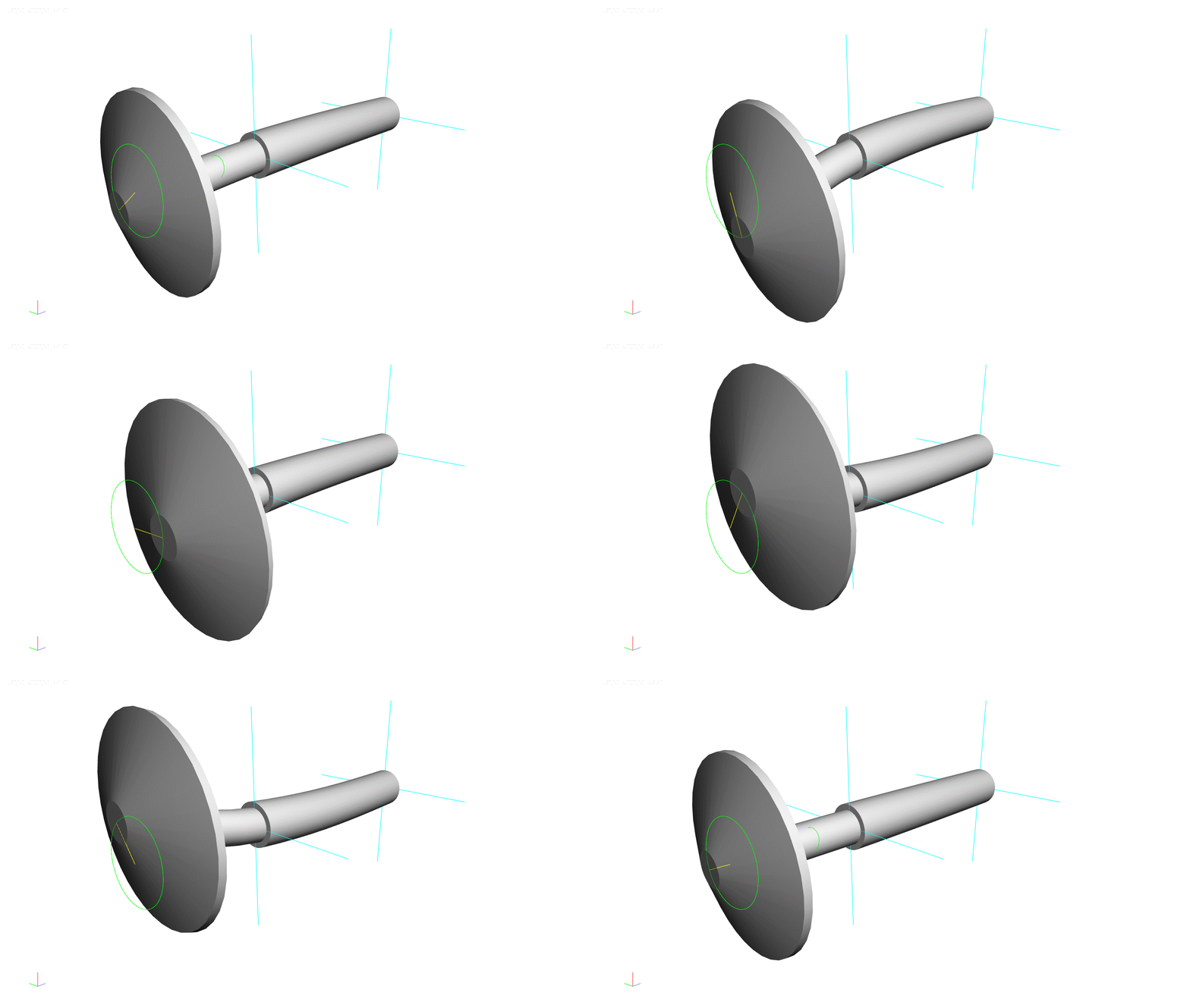
Some of my other blogs have touched on how important it is to consider manufacturing methods during the design phase. This one will show exactly how manufacturing methods impact performance. We will look at three different radial compressor designs to demonstrate the effects of different parameterizations needed for different manufacturing methods. These designs cover a fairly broad range of pressure ratio, Mach number, and Reynolds number. The table below shows some properties of the stages and figures shows the three dimensional shapes.
Stage Properties of the Three
Radial Compressor Baseline Designs
| |
Pressure Ratio
|
Machine Mach
|
Machine
Re
|
Inlet tip Mach
|
|
comp_rad_PR1p2
|
1.2
|
0.49
|
1.8E+06
|
0.41
|
|
comp_rad_PR2p0
|
2.0
|
1.00
|
1.2E+06
|
0.8
|
|
comp_rad_PR5p0
|
5.0
|
1.52
|
5.7E+07
|
0.9
|
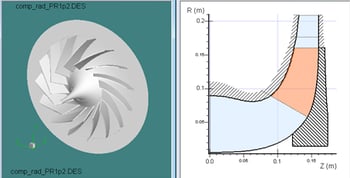
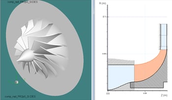
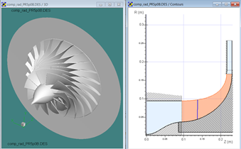
Low (Top), Moderate (Middle), and High (Bottom) Pressure Ratio Baseline Stage Designs
Each of the three compressor designs were modified with three different parameterizations creating a 3x3 matrix of cases. The standard, or baseline parameterization, was a ruled element open wheel design. The three variations on this baseline parameterization were:
-
Integral Shroud – This variation uses a shroud that is integrated with the blades and cut from a single piece of metal. The aerodynamic effect of this is a shroud that rotates with the passage. The improvement resulting from this effect has to be traded off with additional losses from a secondary leakage path over the shroud.
-
Point Milled Design – A point milled design adds another degree of freedom in shaping the blade. Profiles between the hub and shroud can be specifically controlled with this parameterization which allows the designer more control over incidence distributions.
-
Cutback Leading and Trailing Edges – These designs cut back the leading and/or trailing edges across the ruled elements. The aerodynamic effect of this is parameterization is generally small but the approach enables a more efficient cutting process and potentially better surface finish.
The stage variations were analyzed using Concepts NREC’s Pushbutton CFD™ solver. Pushbutton CFD uses a third-order AUSM scheme, along with advanced grid topologies customized for turbomachinery. Several turbulence models are available and the model used in this study was the single equation Spalart-Allmaras model. The grid resolution averaged about y+=20 for all cases.
Figure below shows some raw data of total-to-total efficiency verses mass flow for the three baseline compressor stages (dashed lines) compared to a variation on each of these designs using an integral shroud (solid lines). The design point, nominally the best efficiency point, is shown with a black dot.
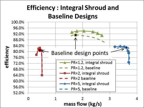
Total-to-Total Efficiency Versus Mass Flow for the Three Baseline Designs (Dashed Lines) and Integral Shroud Designs (Solid Lines)
To better visualize the effect of a given parameterization variation, the results were plotted on a normalized basis. The reconfigured plots use mass flows normalized by the baseline design mass flow and the efficiency minus the baseline best efficiency point. By this definition, the baseline design points all have nominalized mass flow of 1 and an efficiency difference of 0 and all pass through the same point on the graph. The plot below shows an example.
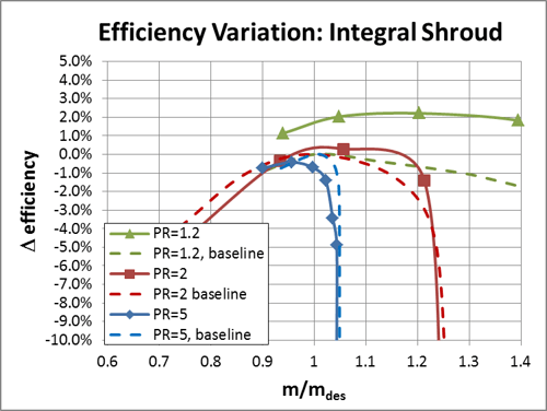
Integral Shroud Designs (Solid Lines) Compared to Baseline Designs (Dashed Lines). Results are Shown in Terms of Total-to-Total Efficiency Minus Baseline Design Point Efficiency
Integral Shroud verses Flank Milled Design
In this first design variation, we’ll examine specifically the differences between a standard flank milled design and more expensive manufacturing method of an integrally shrouded compressor impeller on each of these stages. As previously mentioned, the primary aerodynamic benefit is the advantage of keeping the velocity of the shroud surface relative to the passage at zero.
Several factors come into play in the decision to incorporate an integral shroud or use an open impeller. This is often driven by the ability of the bearing and shaft system to hold the tight clearance levels required for adequate open impeller performance. Often times, in-line machines (where the impeller sits between bearings) require an integral shroud arrangement. The primary aerodynamic benefit for an integral shroud design is the advantage of keeping the velocity of the shroud surface relative to the passage at zero.
The figure below shows the total-to-total efficiency for the three compressor stages for both the open baseline designs (dashed lines) along with the integral shroud (solid lines) variation.
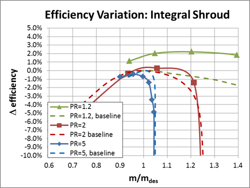
Integral Shroud Designs (Solid Lines) Compared to Baseline Designs (Dashed Lines). Results are Shown in Terms of Total-to-Total Efficiency Minus Baseline Design Point Efficiency
The results, for the most part, show a modest improvement in the stage efficiency with the integral shroud design. The low pressure ratio design (green line) shows more noticeable improvement with very little in the two higher pressure ratio designs. This improvement is primarily a function of higher clearance for the low pressure design and hence the larger improvement in this case. The overall effect is vertical shift in the efficiency curve, with very little effect on range or peak efficiency location.
The cost of milling an integrally shrouded rotor can be 5 times or more the cost for an open flank milled rotor. It is important to note that sometimes a shrouded design cannot be milled because the tool can’t physically fit into the middle of the flow path. Occasionally, a combination of milling and EDM (Electrical Discharge Machining) is available for hard to reach parts of integral shroud impellers.
Point Milled Design verses Flank Milled Design
Point milling gives additional control over the final shape over flank milling. A flank milled design really only allows explicit definition of the cross-sectional blade profile at the hub and shroud. The streamline shapes in between the hub and shroud are essentially fixed by the restriction of the ruled element layout. In contrast, point milled designs allow more controlled variation across the span. In this example, we varied the center profile and explicitly set the inflow angle there to achieve a more desirable incidence distribution. The figure below shows the distribution of incidence as a function of passage span for the PR=2 design for both the baseline ruled element (solid line) and the point milled variation (dashed line). Note the more even distribution for the point milled design.
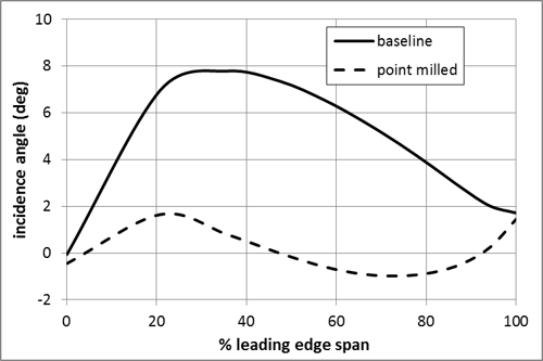
Leading Edge Incidence Distribution of the PR=2 Design for the Baseline (Solid Line) and Point Milled (Dashed Line) Design
This more even incidence distribution can generally be considered a more desirable design improvement, although the ideal incidence distribution might have some real variation. Variables such as Mach number distribution, thickness distribution, choke passage area will all influence the optimum incidence distribution around the leading edge region. This ideal can only be determined with an optimization study using high-end CFD analysis. No attempt was made to modify the shape much beyond the leading edge region in this example. The blade angle distribution was feathered in to give a nearly identical shape at the trailing edge to the baseline. The figure below shows the overall effect of the point milled design using the normalized efficiency basis from the baseline case explained previously.
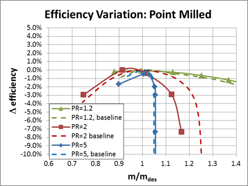
Point Milled Designs (Solid Lines) Compared to Baseline Designs (Dashed Lines). Results are Shown in Terms of Total-to-Total Efficiency Minus Baseline Design Point Efficiency
The overall effect of the modified point milled design over the baseline is fairly modest compared to the integral shroud option. Only the moderate pressure ratio case (PR=2) shows a significant difference. In this case, the difference is due to the decreased choke margin that resulted from the more tangent blade angle at the center of the passage. This reduced the throat area for this design and therefore the maximum mass flow. The driving force behind the more significant difference in the PR=2 design was the higher level of curvature in the inlet region over the other designs. The curvature induced more variation in the velocity triangle at the leading edge and resulted in a larger blade angle variation than the other designs which had straighter inlet sections. Manufacturing time is approximately 30% longer using point milling compared to flank milling. Cost sensitive turbochargers industry for example, almost always use flank milling.
Cutback Leading and Trailing Edge verses Flank Milled Design
Cutback leading edges can be used to improve the part quality from the 5-axis machining. The process produces a subtle but definite variation in the three dimensional shape of the design which can affect the overall performance. The motivation of the layout is to reduce the “swing angle” (sweep in cutting tool angle between the leading and trailing edges of the impeller). The process still maintains an overall ruled element shape to the passage but requires a point milled secondary step near on the cutback edges. The technique distributes the ruled element lines into a more parallel distribution. The extended element “sheet” crosses over the cutback leading and trailing edges leaving a “virtual impeller” (shown in orange in the figure below). The extended sections are then cut back to the original meridional cross section. If laid out with care, the primary aerodynamic parameters such as incidence and passage cross section are only minimally changed. The figure on the right below shows the cutback design (gray) overlaid on the baseline (orange). The resulting shape gives a curved shape to the edges even though the basic layout is still ruled elements.
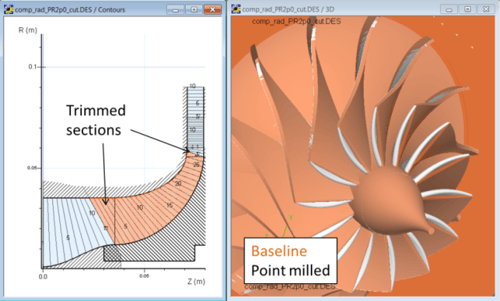 Comparison of Baseline and Cutback Design Variations for PR=2 Compressor Design
Cutback designs can allow more aggressive cutting since acceleration of the cutting head is lower due to lower turning requirements. The reduced acceleration tends to produce fewer defects in the surface of the finished part and can increase the life of the cutting machine.
Compared to the other design variation described above, the effect of the cutback on performance was quite a bit smaller. This is not too surprising since the overall change in shape of this method is comparatively small. The overall effect parallels the point milled study in that the biggest influence is a slightly different throat shape for moderate pressure ratio design (in red). The resulting throat was slightly smaller with the cutback edge and so the choked mass flow was slightly less as a result.
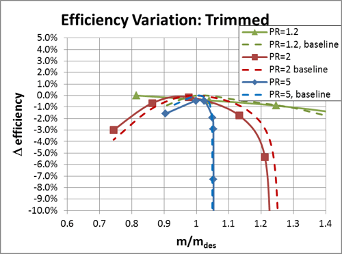
Cutback Designs (Solid lines) Compared to Baseline Designs (Dashed Lines). Results are Shown in Terms of Total-to-Total Efficiency Minus Baseline Design Point Efficiency
The primary benefit is a smoother machine motion with the cutback variation a better surface finish that can result with little impact to milling time. The figure below shows an actual example of impeller with cutback edges (right) compared to an equivalent uniform ruled element design. The improvement in surface finish is clearly evident.
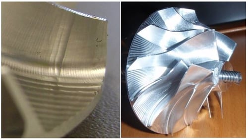 Original 90-Degree Swing Part Showing Surface Defects (Left); Cutback Design Showing a High Quality Surface Finish (Right)
The examples shown clearly demonstrate some of the trade-offs in performance that result from the different parameterizations that various manufacturing methods require. It is important to remember that although manufacturing is the end process, the performance of the design is influenced by the parameterization required of the manufacturing method. This needs to be considering at the earliest stages of the design process.
Computer‐aided design systems like Concepts NREC's Agile Engineering Design System make it possible to consider all of these possibilities and analyze the trade-off involved. Only by weighing all the possibilities and considering the entire process from initial design to end manufacturing process can the best end result be achieved.


 Comparison of Baseline and Cutback Design Variations for PR=2 Compressor Design
 Original 90-Degree Swing Part Showing Surface Defects (Left); Cutback Design Showing a High Quality Surface Finish (Right)