Why Meanline Scripting is Becoming Essential for Turbomachinery Design
Manual meanline design can sometimes feel less like design and more like managing a chain of tiny decisions.


If you design turbomachinery for a living, you are already doing multidisciplinary optimization (MDO), regardless of whether you have a special software tool with MDO built in or not. Turbomachines, by their nature, require advanced fluid dynamics as well as very high mechanical complexity. Whenever you make a trade-off between performance and durability or performance and weight/inertia, you are doing an MDO study. Adding MDO software to your traditional design approaches can give you additional insight into the trade-offs, and save you time by avoiding the need for manual iteration.
In the example below, we are designing a radial compressor for use in a turbocharger. The goal is to maximize aerodynamic efficiency and pressure ratio, while at the same time minimizing the polar moment of inertia, deflections, von Mises stress, and meeting the frequency requirement for the first blade flapping mode.
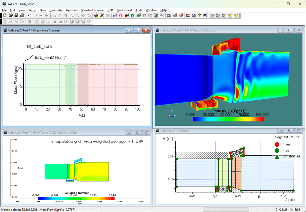
Using the Pushbutton FEA™ package inside of the AxCent® geometry engine, the designer has simultaneous access to the mechanical geometry of the impeller wheel, both inside and outside of the primary flow path.
The design variables in the optimization are as follows:
Aero and Mechanical Variables
Mechanical Only Variables
Figure 1 illustrates each of the mechanical design variables from Pushbutton FEA that were used in the MDO.
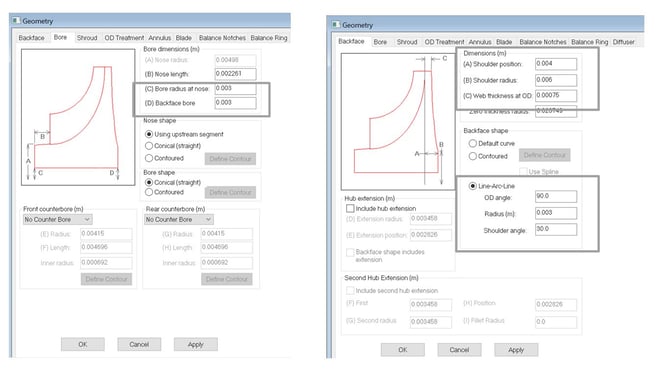
Figure 1—Mechanical Geometry Parameters
The MDO had the following objectives and constraints:
The MDO was set up by using TurboOPT II™ to connect the geometry engine AxCent together with FEA solver Pushbutton FEA and the CFD solver FINE™/Turbo. The 3rd party Optimizer modeFRONTIER was used to run the optimization.
With MDO there is no single “best” result. Instead, the postprocessor allows the design engineer to visualize the trade-offs between the objectives. For example, Figure 2 below shows the trade-off between efficiency and moment of inertia.
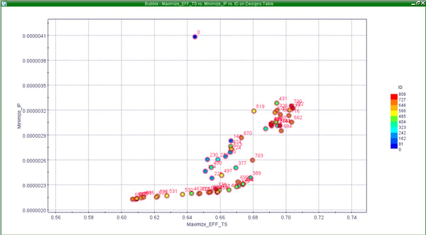
Figure 2—Design Trade-off Between Moment of Inertia and Aerodynamic Efficiency
In general, you can see that higher efficiency is possible with higher inertia, but the highest efficiency design does not necessarily have the highest inertia. Another thing that the MDO analysis shows is how each of the design variables affects the goals and constraints. For example, in Figures 3 and 4, the largest driver of pressure ratio is the impeller radius. The largest driver of peak stress is the exit blade angle (backsweep).
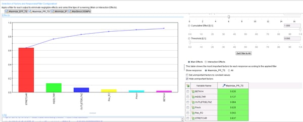 Figure 3—ANOVA of Geometry Parameters with Respect to Pressure Ratio
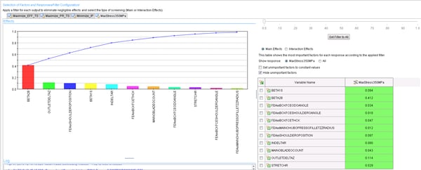 Figure 4—ANOVA of Geometry Parameters with Respect to von Mises Stress
Another useful MDO postprocessing tool is the self-organizing map. In these maps, each design is located in the same (x,y) coordinate. The maps can then be colored by any of the inputs or outputs. The idea would be that one could not only determine which input has the largest impact on a given output, but whether the relationship is direct or inverse. The maps shown in Figure 5 show that the inlet blade height (INDELTAR) is strongly correlated to the natural frequency. In fact, when the inlet blade height is at a minimum, the frequency is at a maximum (inverse relationship).
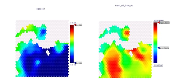
Figure 5—Self-Organizing Maps for Inlet Blade Height and 1st Natural Frequency
In conclusion, MDO software is not a magic solution to push a button and get an optimized design, but rather a useful tool to allow the designer to evaluate and visualize sensitivities and trade-offs, resulting in better overall designs produced in less time.
Tags: CAE Software

Manual meanline design can sometimes feel less like design and more like managing a chain of tiny decisions.

For most turbomachinery engineers, optimization isn’t a new idea. It’s a critical part of their workflow that can’t be overlooked. But sometimes that crucial step isn’t easy to get to.
It’s no secret that turbomachinery design has been one of the most demanding CAE environments, thanks to tight tolerances, complex physics, and long design cycles. That hasn’t changed in 2026, but...