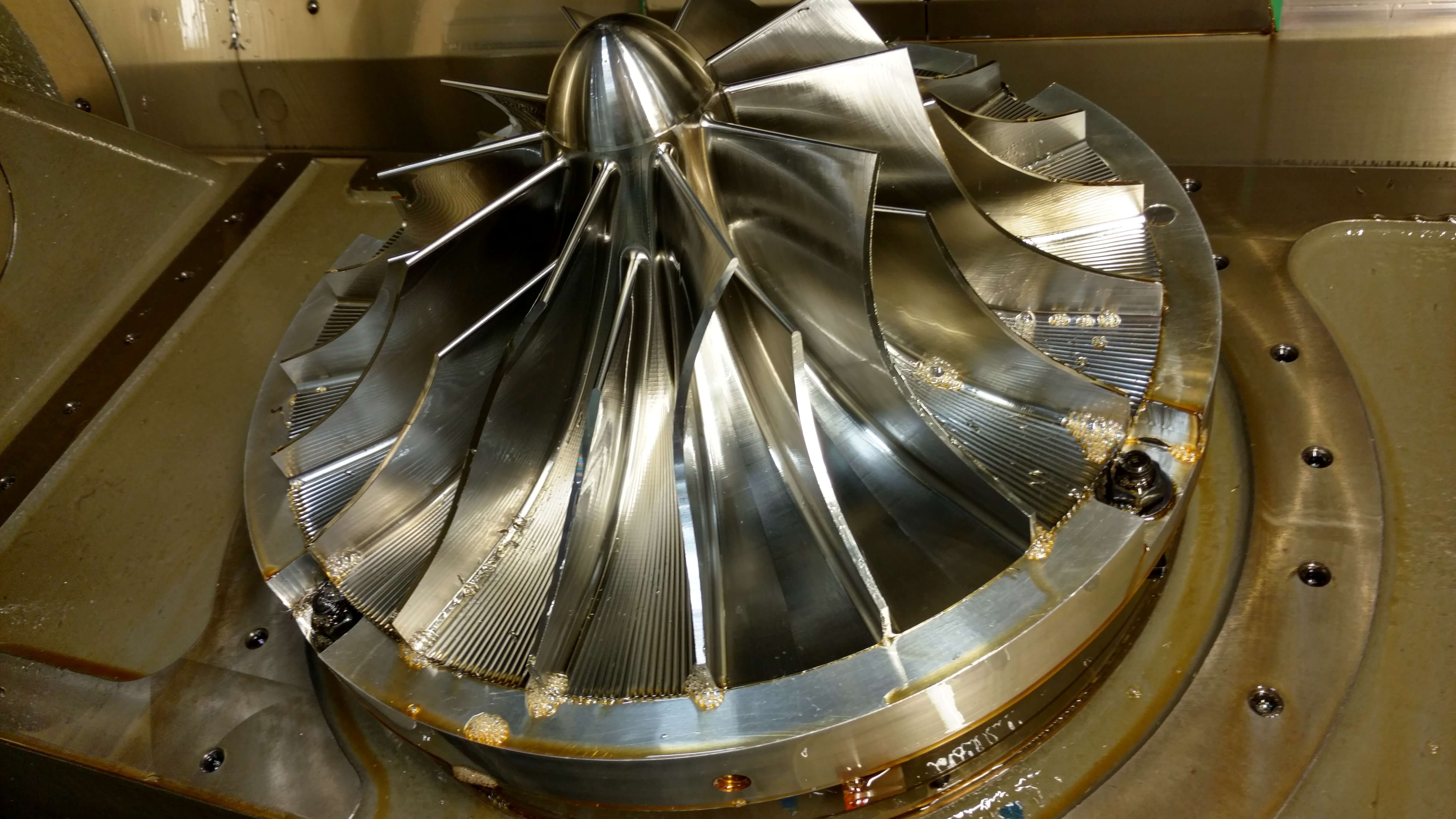
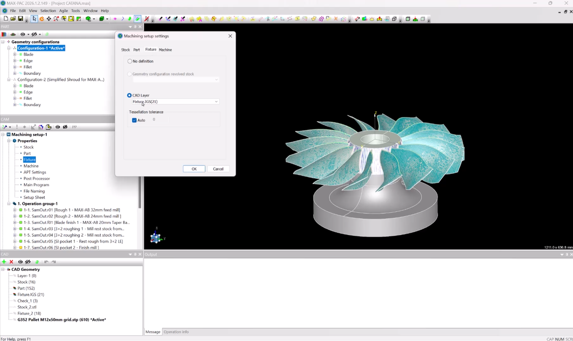
Five-axis machining makes it possible to manufacture complex blade geometry by continuously coordinating the position and orientation of the cutting tool relative to the part. That capability, however, requires multiple machine axes to move together as the cutter follows the programmed tool path.
During that movement, the machine’s rotational axes may need to slow, stop, and change direction. These axis reversals in blade machining are a normal part of five-axis machining and aren’t necessarily a problem on their own. But when a reversal occurs while the cutter is engaged with the blade, even a small change in machine motion can affect the resulting surface and, in some cases, leave a visible witness mark.
Understanding what causes these reversals, where they occur within a tool path, and how they affect the surface finish can help programmers improve blade surface quality by reducing axis reversals.
What Causes Axis Reversals in Blade Machining?
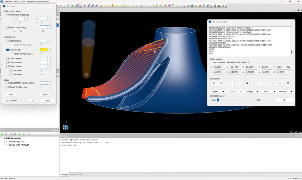 Head reversals shown in MAX-PACTM
A machine axis reversal occurs when an axis that has been moving in one direction slows to a stop and then begins moving in the opposite direction. While the concept itself is simple, these changes in direction become more significant in 5-axis machining, where several axes must move together to maintain the required position and orientation of the cutting tool.
In addition to movement along the machine’s linear X, Y, and Z axes, 5-axis machines use two rotational axes to orient the tool relative to the part. Depending on the machine configuration, that rotation may come from movement of the machine head, the table, or a combination of both. A head reversal occurs when a rotational axis controlling the orientation of the machine head changes direction, while a table reversal occurs when a rotational axis controlling the table changes direction.
Blade geometry requires the cutter to continuously change its position and orientation as it moves across the surface. As the required tool orientation changes, the machine’s rotational axes must respond accordingly. Depending on the blade geometry, programmed tool path, and machine configuration, a rotational axis may reach a point where continuing along the tool path requires it to stop moving in one direction and begin moving in another.
This means that even when the programmed tool path is mathematically smooth, the motion of each individual machine axis may not be. The tool can continue along the blade surface while one of the rotational axes changes direction to maintain the required tool orientation.
How Axis Reversals Can Affect Blade Surface Quality
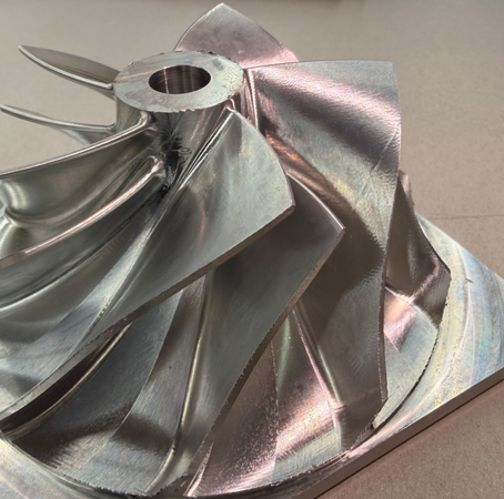 Example of a witness mark caused by an axis reversal on a finished impeller
When a rotational axis reverses direction, it cannot transition from moving one way to moving the other instantaneously. The axis must decelerate, come to a stop, and then accelerate in the opposite direction, all while the machine continues coordinating the movement of the other axes.
If this transition occurs while the cutting tool is engaged with the blade, the change in machine motion can affect how the tool moves across the surface. Even a small variation in the cutting tool’s movement or contact with the part can leave a visible mark on the finished blade.
Not every axis reversal will produce a noticeable witness mark – a visible surface imperfection that appears where the change in machine motion occurred – but when witness marks consistently correspond with locations where a rotational axis changes direction, the reversal may be an important factor to look at.
Identifying Axis Reversals Before Machining
Looking at the tool path alone may not reveal how each individual machine axis will behave as the cutting tool moves across the blade. A tool path that appears smooth can still require a rotational axis to change direction at certain points along the surface.
Evaluating the corresponding machine motion before machining begins can help programmers identify where these reversals occur and determine whether they coincide with areas where surface quality could be affected. This provides an opportunity to recognize potential problem areas before they appear as witness marks on the finished part.
By looking beyond the tool path to the movement of the machine itself, programmers can better understand what may be contributing to a surface finish imperfection and where adjustments to the tool path may be beneficial. CAM software designed specifically for turbomachinery can help programmers account for machine motion as they develop and refine tool paths for complex blade geometry.
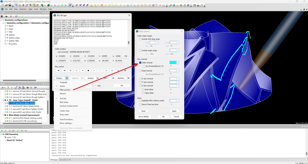 Identifying axis reversals in MAX-PACTM
Reducing Axis Reversals in Blade Machining Through Tool Path Optimization
Because the programmed tool path determines how the machine’s axes move, changes to the tool path can also change where and how rotational-axis reversals occur. In some cases, adjusting the tool path can smooth the transition through a reversal or eliminate a problematic reversal altogether.
The goal is not only to generate a tool path that produces the correct blade geometry, but also to consider how the CNC machine will physically execute that path. The best adjustment will be unique to each situation and depend on factors such as the blade geometry, tool path, and machine configuration.
Being able to identify these reversals and understand their relationship to the finished surface gives programmers another way to evaluate and optimize 5-axis blade machining operations before cutting the part.
For a practical demonstration, watch our webinar, How to Improve Blade Surface Quality by Reducing Axis Reversals in MAX-PAC™. We’ll walk through a real machining example and show how to identify head and table reversals, evaluate their effect on machine motion, and make tool path adjustments to reduce them.