Why Meanline Scripting is Becoming Essential for Turbomachinery Design
Manual meanline design can sometimes feel less like design and more like managing a chain of tiny decisions.


A common struggle for mechanical engineers using Computer Aided Engineering (CAE) tools is the time-consuming process of moving geometry between the CAE system and Computer Aided Design (CAD) software. This blog will explore ways to reduce time spent on this process.
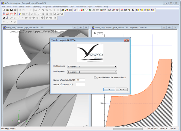
One way to save time is to bypass CAD in the CAE process until it is necessary. For example, look at the need to perform computational fluid dynamics (CFD). CFD requires knowledge of the full three-dimensional geometry. All general purpose CFD packages start their training by showing users how to import geometry from CAD. This usually involves defeaturing the geometry and cleaning up small gaps between surfaces to create “watertight” CAD models. The cleanup of CAD models to be meshed and run in general purpose CFD is extremely time consuming, and generally unnecessary when designing turbomachinery because we are not designing some general geometry. Specialized design systems like the Agile Engineering Design System® from Concepts NREC can facilitate the jump from design intent directly to CFD mesh without the need for a watertight 3D CAD model. With a single mouse click, aero engineers can mesh and solve their designs in the NUMECA FINE™/Turbo CFD package.
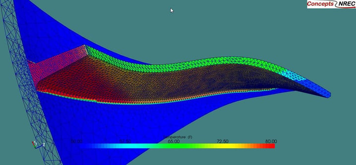
Next, consider finite element analysis (FEA) to calculate stress and vibration. Analogous to CFD, suppliers of general purpose FEA codes have designed their workflows to include a time-consuming CAD import step before meshing and analysis can be performed. When designing turbomachinery blading and flow paths for optimum aerodynamic performance, the engineer also needs to consider the stress and vibration. The issue is that certain geometry that does not touch the primary flow (such as the backface shape of an impeller or blisk shape below the hub) is critically important for FEA analysis. The usual workflow is to export the aerodynamic geometry to a CAD system, build the additional structural pieces in CAD, and then export to the FEA software. Pushbutton FEA™ allows engineers to eliminate the transfer from aero design to CAD, as well as the subsequent export from CAD to FEA tool. Pushbutton FEA enables the aero engineer to design the structural geometry in the same environment as the aero geometry. Once the geometry is designed, the Agile system creates a mesh for FEA. This mesh can then be solved in the Pushbutton FEA solver, or used by general purpose FEA codes.
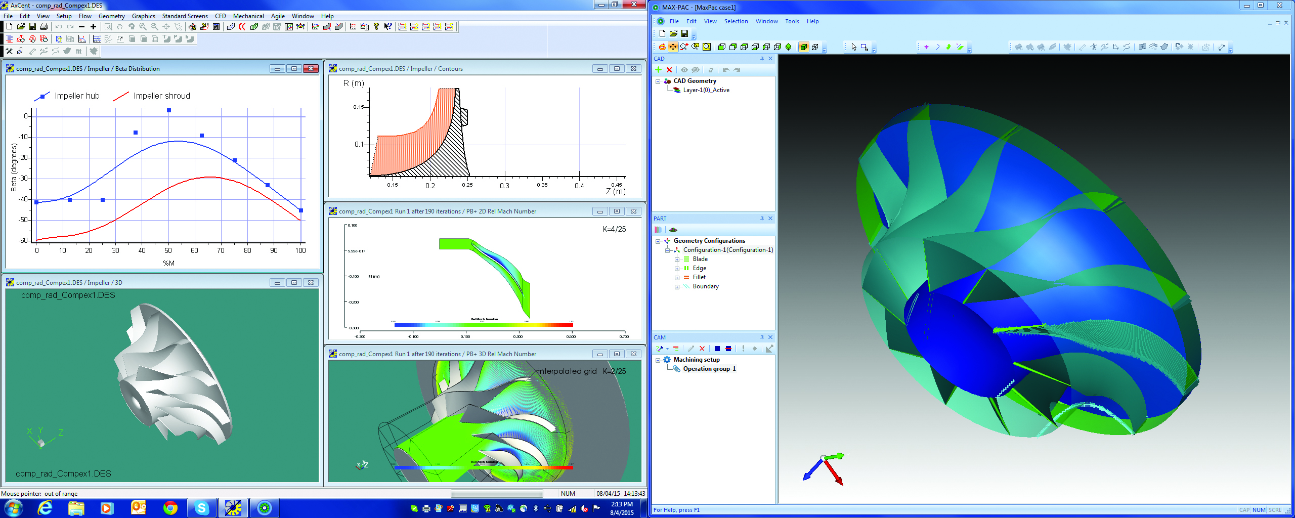
Finally, let’s examine the process starting from the turbomachinery design and proceeding to the Computer Aided Manufacturing (CAM) software. Many turbomachine components are made using 5-axis numerical machining. Most centrifugal compressor impellers and axial bladed disks are made in this manner. General purpose CAM software includes a CAD import capability which generally requires that the CAD geometry be cleaned up and prepared in a certain way. Again, this is time consuming. Our specialized MAX-PAC™ software for 5-axis machining of impellers and blisks is no different in that it includes an extensive CAD import capability. Where it differs is for customers who have both AxCent® for turbomachinery geometry design, and MAX-PAC. They have a direct link between the two systems so that the design intent can be converted to machining instructions without the need to use a CAD system.
CAD certainly has its place in the product design process, and eventually all products need to be fully-defined in CAD, just be sure you are not doing too early or too often in the design process.
Tags: CAE Software, CAM Software, MAX-PAC, CAD

Manual meanline design can sometimes feel less like design and more like managing a chain of tiny decisions.

For most turbomachinery engineers, optimization isn’t a new idea. It’s a critical part of their workflow that can’t be overlooked. But sometimes that crucial step isn’t easy to get to.
It’s no secret that turbomachinery design has been one of the most demanding CAE environments, thanks to tight tolerances, complex physics, and long design cycles. That hasn’t changed in 2026, but...